Acoustic radiating membrane for a music box or striking watch

a technology of acoustic radiating membrane and a music box, which is applied in the direction of sound producing devices, electronic time-pieces, horology, etc., can solve the problems of low acoustic efficiency, limiting adaptation possibilities, and affecting the effect of frequency bandwidth, so as to achieve uniformity of efficiency

Active Publication Date: 2012-06-07
MONTRES BREGUET
View PDF6 Cites 15 Cited by
  • Summary
  • Abstract
  • Description
  • Claims
  • Application Information

AI Technical Summary

Benefits of technology

[0013]Owing to the fact that the ellipses are made in the membrane, twice as many natural vibration modes can be obtained for each ellipse compared to an area of circular shape. The number of natural modes within the audible frequency range is thus maximised, particularly between 1 kHz and 4 kHz. The overall response of the vibrating membrane is thus flattened by removing the circular symmetry and using an asymmetrical area of this type in the form of an ellipse seen in a plan view.
[0014]Advantageously, the membrane may be made of amorphous metal or metallic glass, or also of gold, or even brass or another material having similar density, Young's modulus and limit of elasticity. The arrangement of the asymmetrical areas may also increase the number of natural frequencies in the useful acoustic frequency band, i.e. between 1 kHz and 4 kHz, also in order to increase the overall acoustic level. With this type of membrane, enlargement of the acoustic range may be combined with very low internal damping, which provides very good acoustic efficiency.

Problems solved by technology

In a conventional striking or musical watch, acoustic efficiency, based on the complex vibro-acoustic transduction of the external parts, is low.
The configurations of these external parts are also dependent upon the aesthetic appearance of the watch and operating stresses, which may limit adaptation possibilities.
Generally, with the use of a conventional acoustic radiating membrane, a problem of frequency bandwidth exists.
However, standard uniform membranes never succeed in fulfilling this condition, since the level of response within this frequency range is generally very inhomogeneous.
This is liable to contribute to the corrosion of said membrane where it is in contact with the gold back cover, which is another drawback.

Method used


Image

  • Acoustic radiating membrane for a music box or striking watch
  • Acoustic radiating membrane for a music box or striking watch
  • Acoustic radiating membrane for a music box or striking watch

Examples


Embodiment Construction

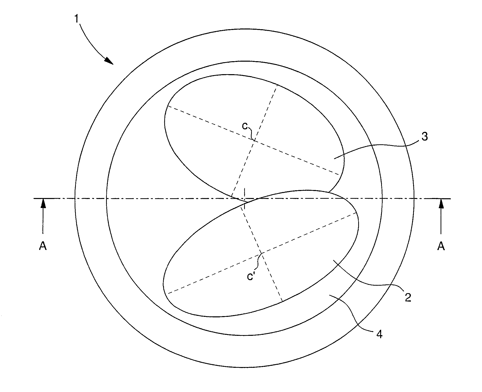
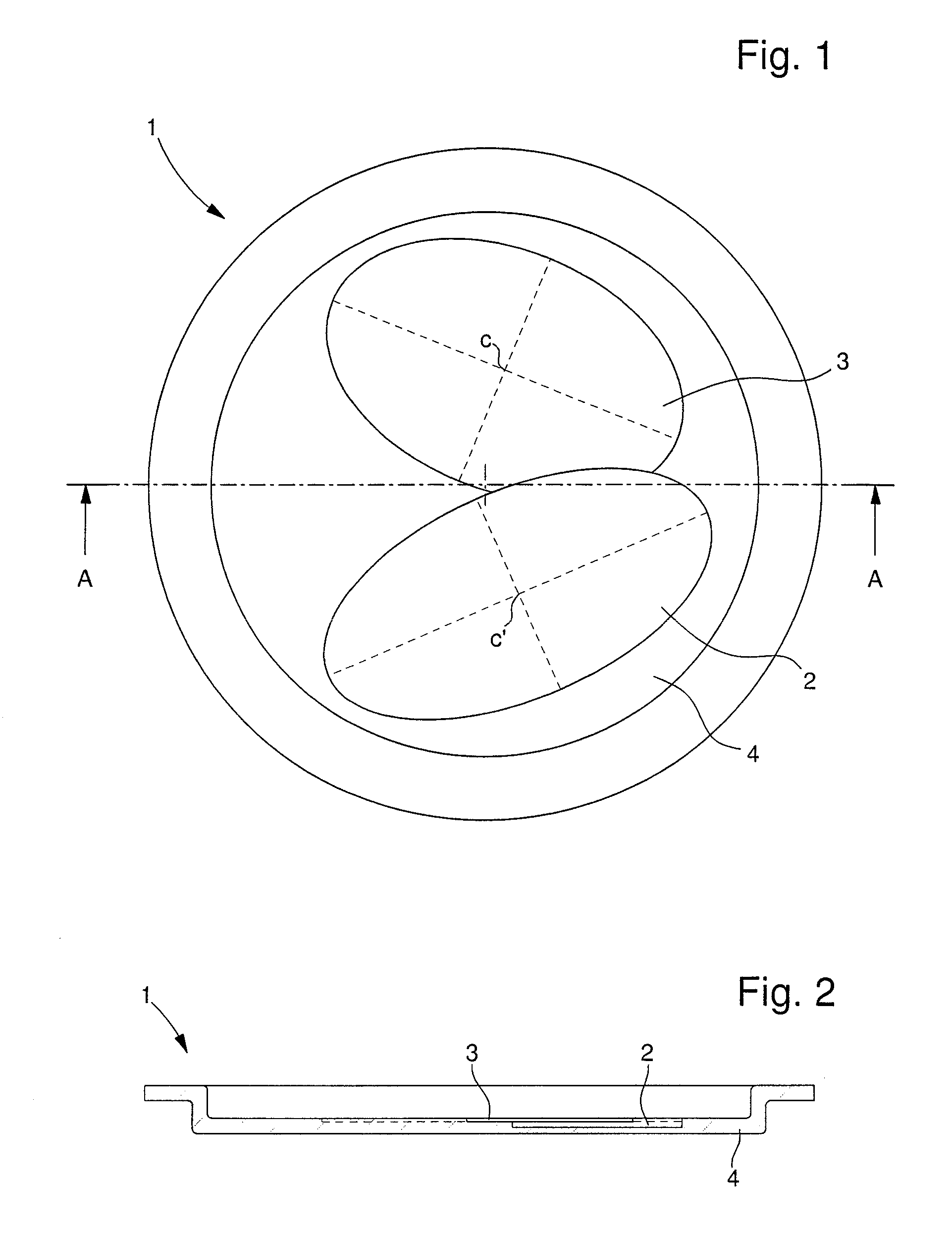
[0022]In the following description, reference will mainly be made to the configuration of an acoustic radiating membrane to be fitted, in particular, to a music box, such as a musical watch, or striking watch.

[0023]FIG. 1 shows a top view of an acoustic radiating membrane 1 for a music box, such as a musical watch, or striking watch. In this embodiment, membrane 1 is made with inhomogeneous spatial thickness, i.e. it includes areas, which have been machined into the total thickness of the membrane. The machined areas each have a different uniform thickness. Seen in a top view, the hollowed out areas of different thickness have asymmetrical circular shapes. The asymmetrical shapes are preferably ellipses 2, 3 hollowed out of a bottom part 4 of a circular membrane 1, which may be dome-shaped, as explained hereinafter with reference to FIGS. 2 and 4. These ellipses 2, 3 are partly superposed. The presence of several asymmetrical circular areas considerably increases the number of natur...


PUM


Abstract

The acoustic radiating membrane (1) is for assembly in a music box or a striking watch. The membrane is made with at least one area of asymmetrical shape, formed in the material of the membrane or with at least one area of asymmetrical shape having a different thickness from the general thickness of the membrane. It preferably includes two asymmetrical areas of elliptical shape (2, 3) which are partly superposed and have a different thickness from each other. The two ellipses (2, 3), preferably hollowed out of the membrane, are off-centre in relation to each other.

Description

[0001]This application claims priority from European Patent Application No. 10193425.5 filed 2 Dec. 2010, the entire disclosure of which is incorporated herein by reference.FIELD OF THE INVENTION[0002]The invention concerns an acoustic radiating membrane for a music box, such as a musical watch, or a striking watch.[0003]The invention also concerns a watch, which includes an acoustic radiating membrane. The watch includes a watch case essentially formed of a middle part and a back cover removably secured in a sealed manner to the middle part. A crystal is arranged on the opposite side to the back cover to close said case in a sealed manner. A timepiece movement is held inside the watch case and provided with a striking mechanism that can be actuated at determined times to produce a sound or music. At least one acoustic radiating membrane is connected to the case to radiate the sound produced by the striking mechanism towards the exterior of the case.BACKGROUND OF THE INVENTION[0004]...

Claims


Application Information

Patent Timeline
Patent Type & Authority Applications(United States)
IPC IPC(8): G04B21/00
CPCG10K13/00G04B37/0075G04G17/02G10K9/20
Inventor SARCHI, DAVIDEFAVRE, JEROMEKARAPATIS, NAKIS
Owner MONTRES BREGUET
Why Eureka
Try Eureka