
Tissue Grasping Forceps & Localizing Needle Holder

a tissue and needle holder technology, applied in the field of single implements with tissue grasping forceps and needle holders, can solve the problems of difficult to manipulate a tissue block that needs difficult to use such forceps, and difficult to grasp a tissue block to be removed during a surgical procedur

Active Publication Date: 2012-06-07
RAY STEPHEN PAUL
View PDF8 Cites 15 Cited by
  • Summary
  • Abstract
  • Description
  • Claims
  • Application Information

AI Technical Summary

Problems solved by technology

The grasping of a block of tissue to be removed during a surgical procedure can be difficult because the grasping forceps typically has only a single set of jaws, usually containing three teeth per jaw, and works best on surfaces parallel to the top of an operating table.
When the surface is perpendicular or at an angle to the flat surface of the operating table, it is difficult to use such forceps because they do not grasp the surface easily.
This makes it difficult to manipulate a block of tissue needing removal.
There is currently no good way to secure the needle to the tissue at the angle and location achieved when the needle was placed.

Method used


Image

  • Tissue Grasping Forceps & Localizing Needle Holder
  • Tissue Grasping Forceps & Localizing Needle Holder
  • Tissue Grasping Forceps & Localizing Needle Holder

Examples


Embodiment Construction

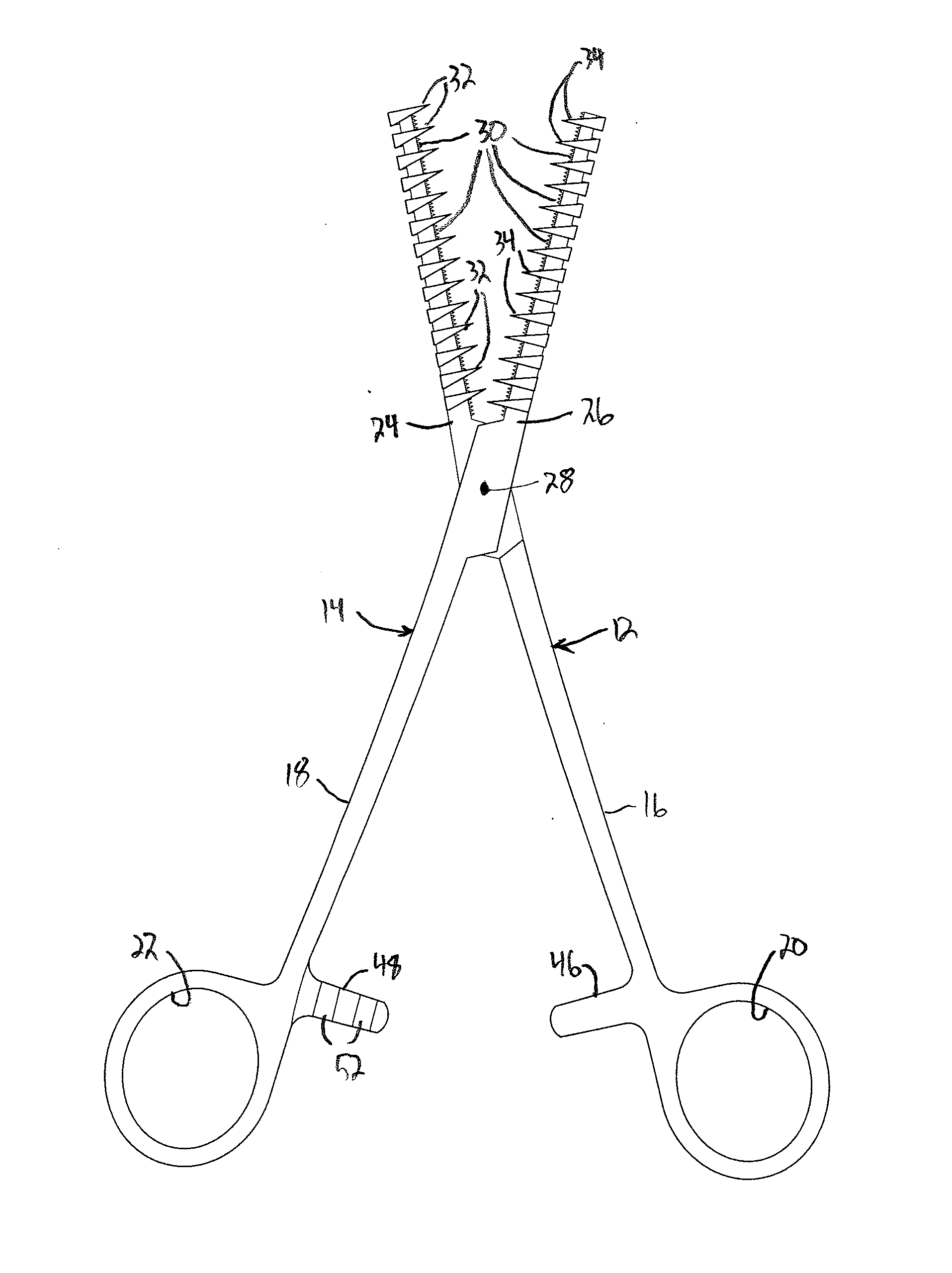
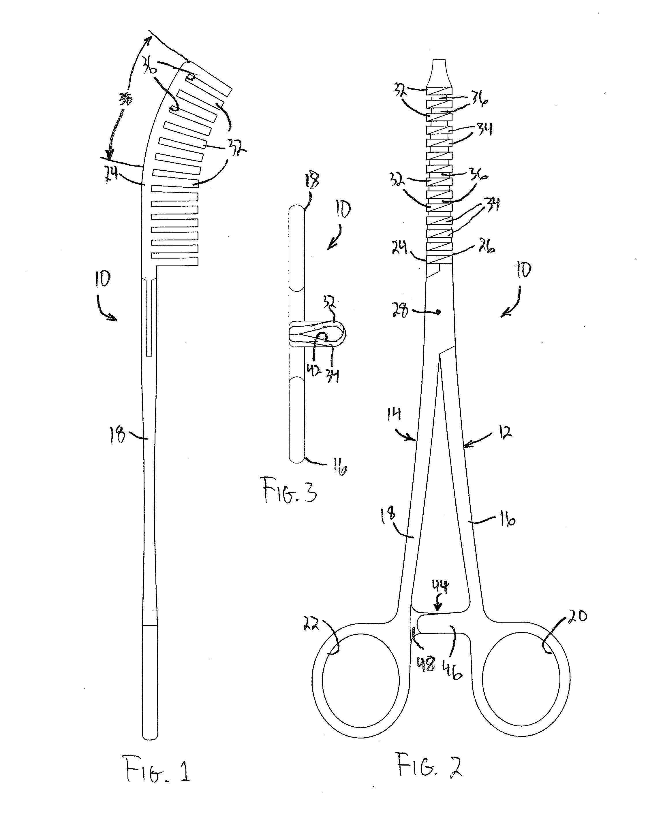
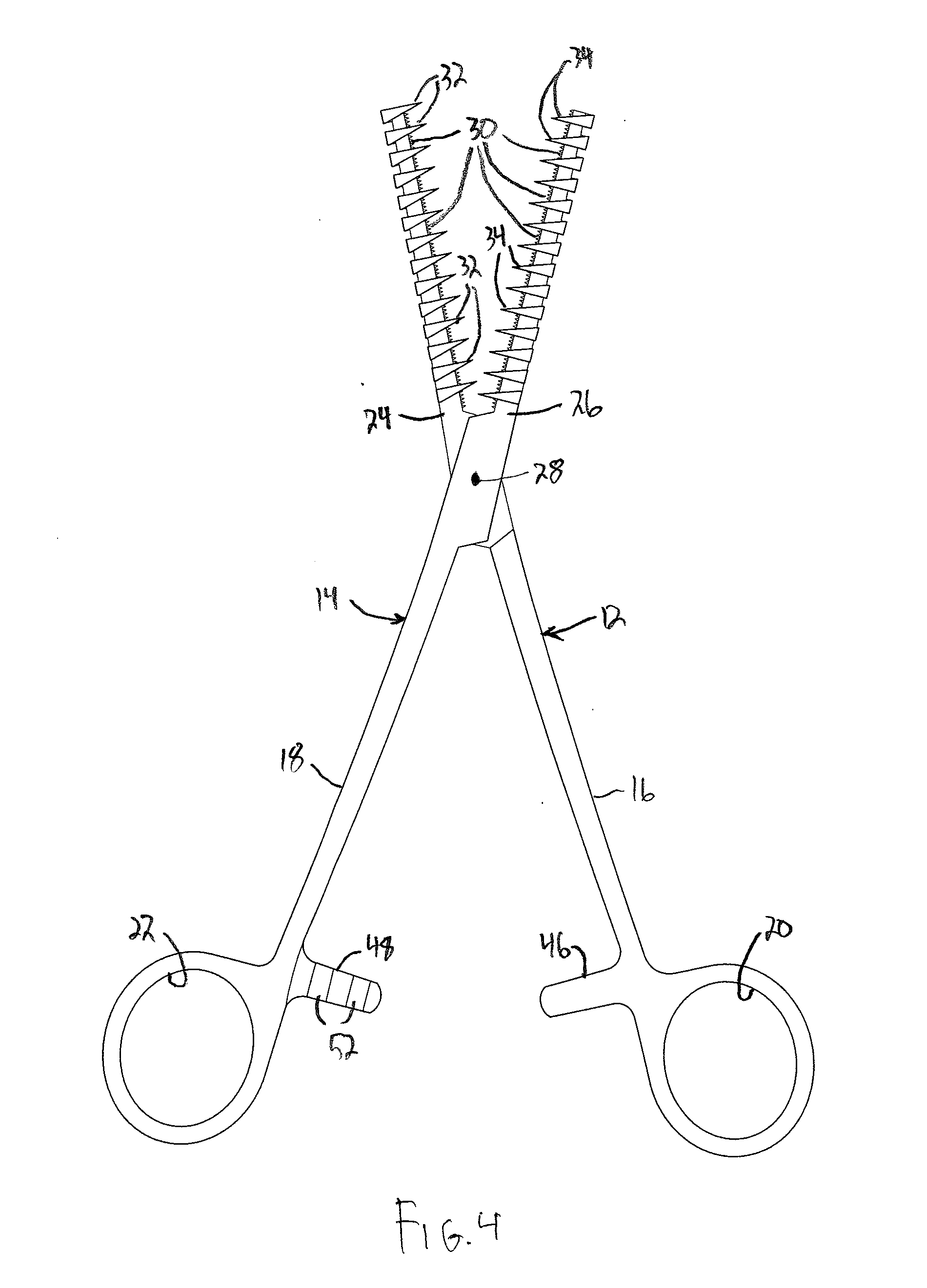
[0016]A tissue grasping forceps and needle holder according to the invention is shown generally at 10 in the drawing figures. It comprises two primary components, a pair of movable arms 12 and 14, with each arm 12 and 14 having a respective handle portion 16 and 18. The respective handle portions 16 and 18 have finger engaging openings 20 and 22, as illustrated. Opposite ends of the arms 12 and 14 include respective working portions 24 and 26, with the handle portion and working portion of each arm being located on opposite sides of a pivot connection 28. The working portions 24 and 26 are shaped to interengage when the handle portions 16 and 18 are in a minimum spaced relation. That minimum spaced relation is best shown in FIGS. 2 and 5. The working portion 24 and 26 disengage when the handle portions 16 and 18 are spaced from the minimum spaced relation, as shown in FIGS. 4 and 6.

[0017]Each working portion 24 and 26 includes a clamp component and a jaw component. The clamp compone...


PUM


Abstract

A tissue grasping forceps and needle holder. A pair of movable arms are pivotably connected about a pivot connection, with each arm having a handle portion on one side and a working portion on the opposite side of the pivot connection. The working portions interengage when the handle portions are closed to a minimum spaced relation. The working portion has a clamp components and jaw component, with the clamp component comprising a plurality of synchronous teeth located to interlock when the handle portions are in the minimum spaced relation. The jaw component comprises a plurality of regularly spaced tines, with the tines being joined in pairs when the handle portions are in the minimum spaced relation with a gap between the tines, and an interstice between each spaced pair.

Description

BACKGROUND OF THE INVENTION[0001]This invention relates to surgical instruments, and in particular to a single implement having a tissue grasping forceps and needle holder.[0002]The grasping of a block of tissue to be removed during a surgical procedure can be difficult because the grasping forceps typically has only a single set of jaws, usually containing three teeth per jaw, and works best on surfaces parallel to the top of an operating table. When the surface is perpendicular or at an angle to the flat surface of the operating table, it is difficult to use such forceps because they do not grasp the surface easily. This makes it difficult to manipulate a block of tissue needing removal. Grasping of the tissue during the surgical procedure allows its manipulation and facilitates excision.[0003]During certain procedures, such as breast lumpectomy surgery, localizing needles are used to locate a tumor. The amount of tissue around the tip of the needle needing removal is determined b...

Claims


Application Information

Patent Timeline
Patent Type & Authority Applications(United States)
IPC IPC(8): A61B17/28
CPCA61B17/062A61B2017/2837A61B2017/00353A61B17/282A61B17/0469A61B17/0483A61B17/28A61B17/29A61B2017/2926A61B2017/2945B25B7/00B25B7/02
Inventor RAY, STEPHEN PAUL
Owner RAY STEPHEN PAUL
Learn More