
Safety Pen Needle Device

Active Publication Date: 2012-06-14
SHL MEDICAL AG
View PDF4 Cites 30 Cited by
  • Summary
  • Abstract
  • Description
  • Claims
  • Application Information

AI Technical Summary

Benefits of technology

[0010]A main aim of the present invention is to remedy the drawbacks of the safety pen needles of the state of the art and in particular to provide a safety pen needle device capable of performing a proper function with few components.
[0014]There are a number of advantages with the present invention. Because of first guide members coacting with first guide tracks, wherein an actuation sleeve is acting between the hub and the first needle shield, and because of the second guide members coacting with the second guide tracks, a safe and reliable locking of both the first and the second needle shield is obtained with very few components.
[0016]There is thus provided a reliable and functional safety pen needle comprising a small number of components, thereby keeping the production costs at low levels.

Problems solved by technology

Accidental needle sticks from used and thereby contaminated needles expose both hospital personnel and other persons that come in contact with people that self-medicate to the risk of infection from blood-borne diseases.
These needle shields may be useful but they add to the complexity and number of components of the injector.
Further, if the injector is designed to deliver multiple doses, then the needle has to be replaced after each injection.
This adds to the risk of accidental needle sticks and if the injector is arranged with a needle cover, this will be in the way when the needle is to be replaced.
However, probably functioning correctly in covering the needle, the safety pen needle according to '168 comprises a lot of interacting components in order to obtain the desired function, which makes the design rather difficult to manufacture and thereby rather costly.
Since the shield is in contact with an injection site and the shield is moved by a translation movement, i.e. a rotationally axial displacement, the contact between the shield and the injection site i.e. the skin of a patient, is affected by a friction which may result in an ineffective function of the safety pen needle.

Method used


Image

  • Safety Pen Needle Device
  • Safety Pen Needle Device
  • Safety Pen Needle Device

Examples


Embodiment Construction

[0026]In the present application, when the term “distal part / end” is used, this refers to the part / end of the device, or the parts / ends of the members thereof, which during use of the device is located the furthest away from the medicament delivery site of the patient. Correspondingly, when the term “proximal part / end” is used, this refers to the part / end of the device, or the parts / ends of the members thereof, which during use of the medicament delivery device is located closest to the medicament delivery site of the patient.

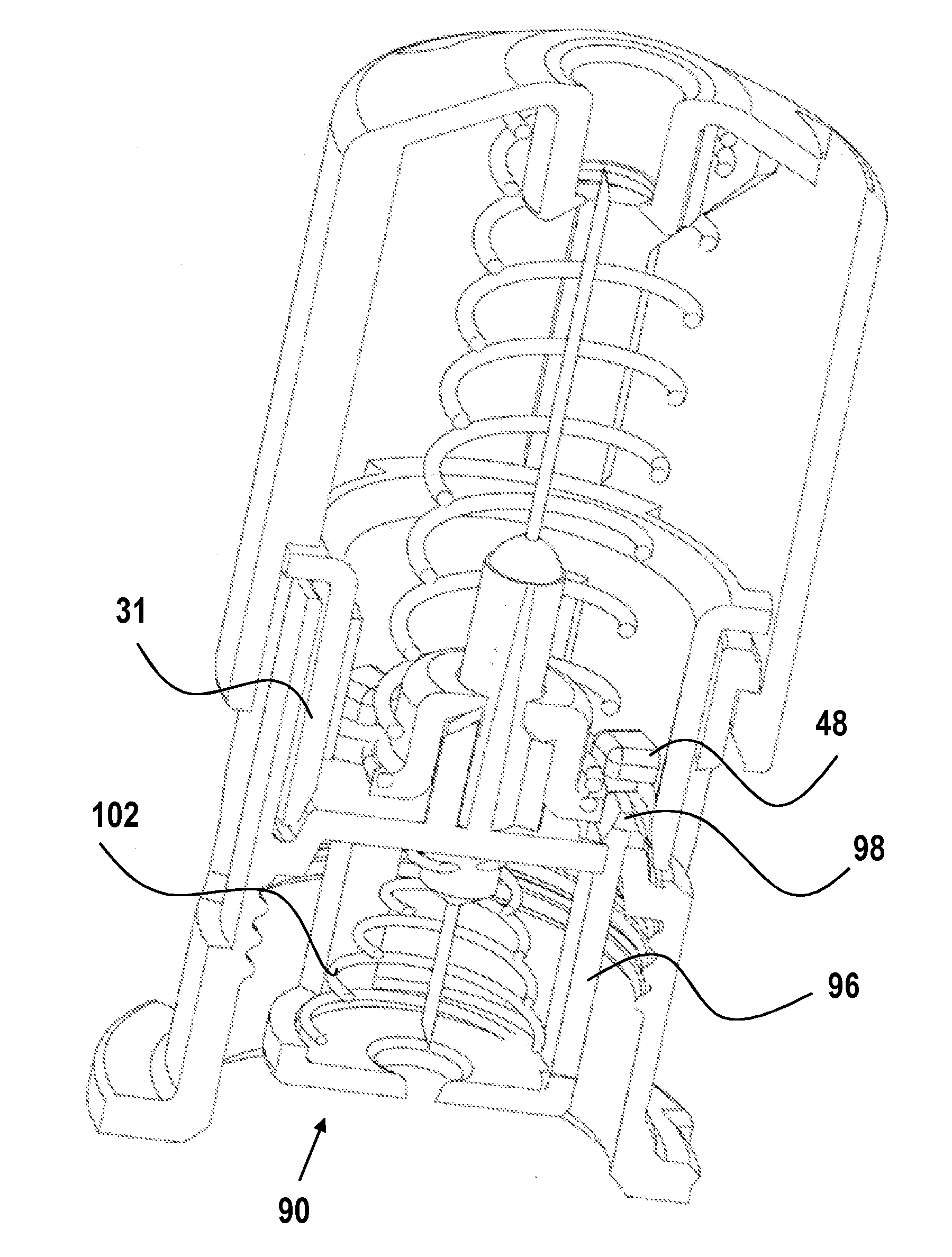
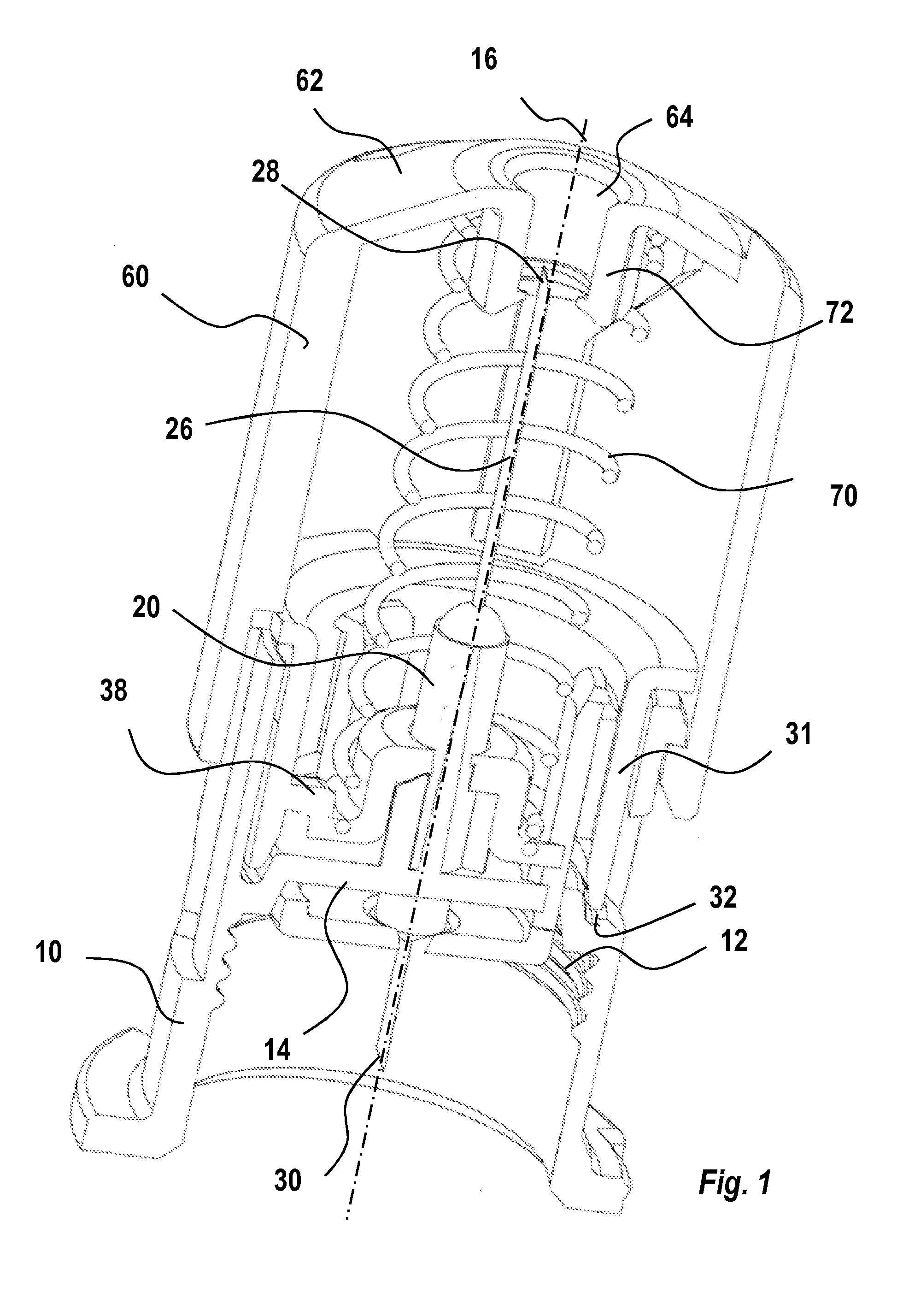
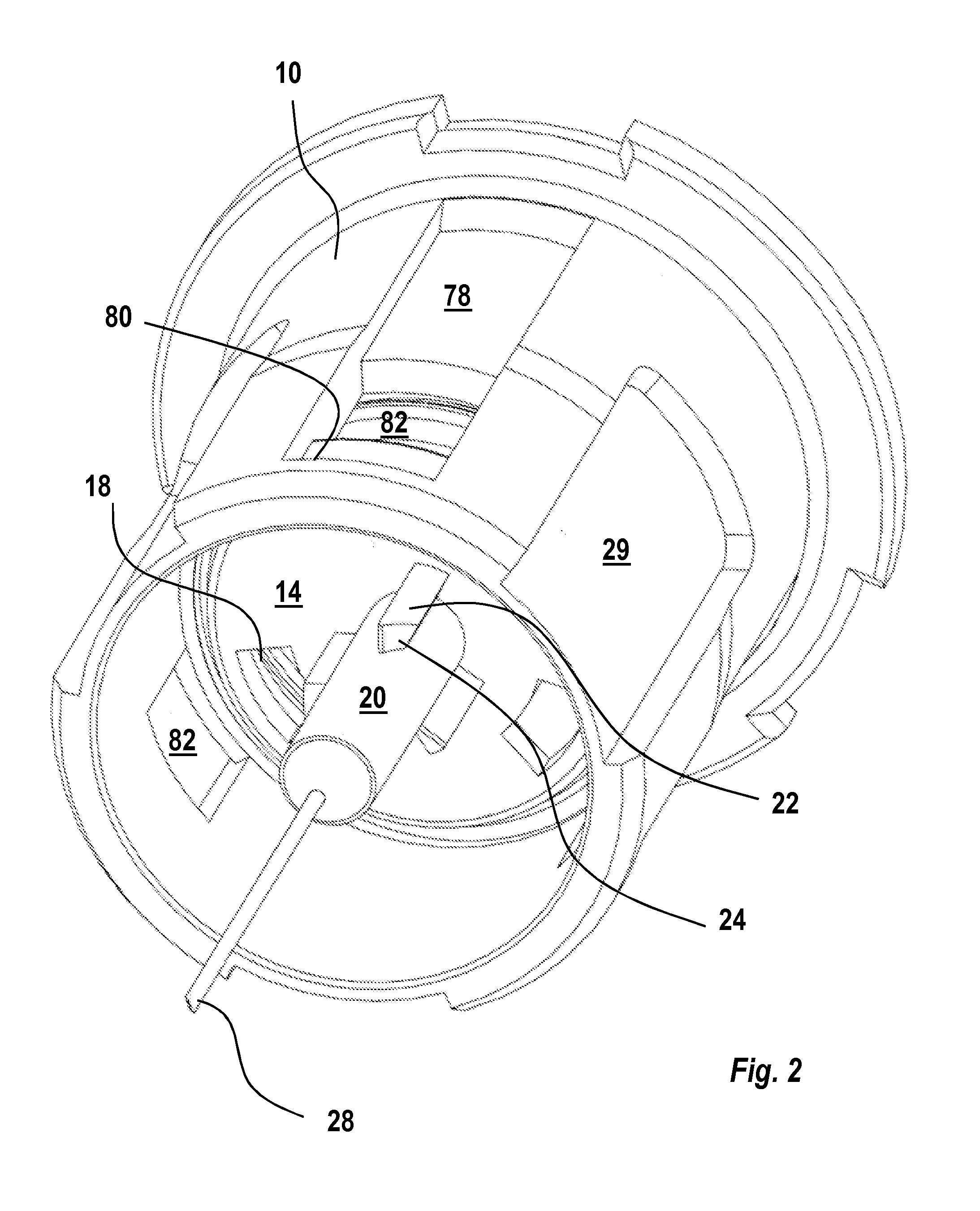
[0027]The embodiment of the present invention shown in the drawings, which is intended to be used with a medicament delivery device, comprises:[0028]a generally tubular hub 10 having a proximal and a distal end, said hub comprising attachment means 12 arranged at its distal end for attaching the safety pen needle device to a medicament container, and a coaxially arranged needle attachment member 20;[0029]an injection needle 26 having an injection end 28 and a n...


PUM


Abstract

The present invention relates to a safety pen needle device comprising a first needle shield (60) and a second back-end needle shield (90). During the injection the first needle shield (60) is moved to en retracted position this movement causes a actuation sleeve (31) to rotate. Said rotation causes a holding member (96, 98) provided on the second needle shield (90) to be released. When the first needle shield (60) is moved from the retracted position to a extended position the actuation sleeve (31) is rotated further so that a first guide member (74) on the first needle shield (60) abuts a first stop member (34) arranged on said actuation sleeve (31). After an performed injection both shields are moved to extended positions by the rotation of an actuation sleeve (31). After the injection the shield are locked it their extended position.

Description

TECHNICAL AREA[0001]The present invention relates to a safety pen needle device to be used with a medicament delivery device and in particular a safety pen needle providing added security against accidental needle sticks.TECHNICAL BACKGROUND[0002]Accidental needle sticks from used and thereby contaminated needles expose both hospital personnel and other persons that come in contact with people that self-medicate to the risk of infection from blood-borne diseases.[0003]Even though the majority of injection devices used are the normal syringe the use of pen needle injectors is becoming more and more popular since they provide the possibility of an easy and convenient self-administration of drugs. The pen-type injectors are also becoming the only choice for certain types of drugs because they are not delivered in ordinary single use syringes.[0004]In order to reduce the risk of accidental needle sticks, many pen injectors have been arranged with needle shields that are capable of cover...

Claims


Application Information

Patent Timeline
IPC IPC(8): A61M5/32
CPCA61M5/326A61M5/3271A61M2005/3267A61M2005/3254A61M2005/3247A61M5/3257A61M2005/3258A61M2205/27A61M2205/273
Inventor KARLSSON, SEBASTIANBRUNNBERG, LENNARTGUILLERMO, CARLOS
Owner SHL MEDICAL AG
Learn More