Straight push type steel dam

A direct-push, steel dam technology, applied in water conservancy projects, marine engineering, coastline protection, etc., can solve the problems that hinder the application and promotion of steel dam gates, high requirements and difficulties in construction and installation, and high manufacturing costs of steel dam gates. To achieve the effect of reasonable force, simplified structure, safe and reliable locking

Inactive Publication Date: 2018-04-20
浙江河好闸门科技有限公司
View PDF10 Cites 4 Cited by
  • Summary
  • Abstract
  • Description
  • Claims
  • Application Information

AI Technical Summary

Problems solved by technology

In order to meet the requirements of strength and rigidity, the bottom horizontal shaft is usually designed to be very thick, and the hoist and related connecting components used to drive the bottom horizontal shaft to rotate are also made very thick, so the manufacturing cost of the steel dam gate is very high.
In addition, due to the large pressure of the water pressure on the gate on the bottom horizontal shaft and the long length of the bottom horizontal shaft, the entire bottom horizontal shaft is bent and deformed, and the bearing used to fix the bottom horizontal shaft on the wall of the lock chamber bears a huge load, and this This kind of bending deformation makes the water-blocking sealing ring used to seal the wall of the lock chamber on the bottom horizontal axis easy to fail, and the water outside the wall of the lock chamber leaks into the lock chamber through the water-blocking seal ring. The motor of the hoist is damaged due to water ingress
In addition, due to the large size and heavy weight of steel dam gates, the requirements and difficulties for construction and installation are high. These problems have seriously hindered the further application and promotion of steel dam gates in water conservancy construction.

Method used


Image

  • Straight push type steel dam
  • Straight push type steel dam
  • Straight push type steel dam

Examples


Embodiment Construction

[0022] The present invention will be further described below in conjunction with the accompanying drawings and specific embodiments.

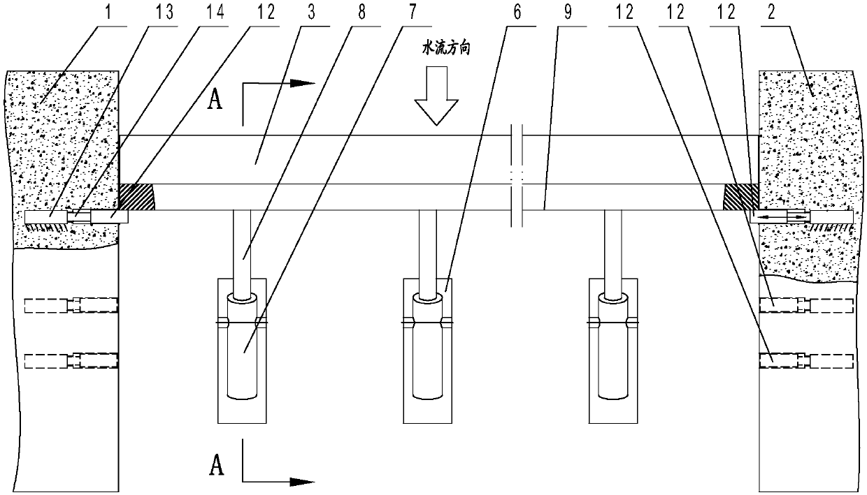
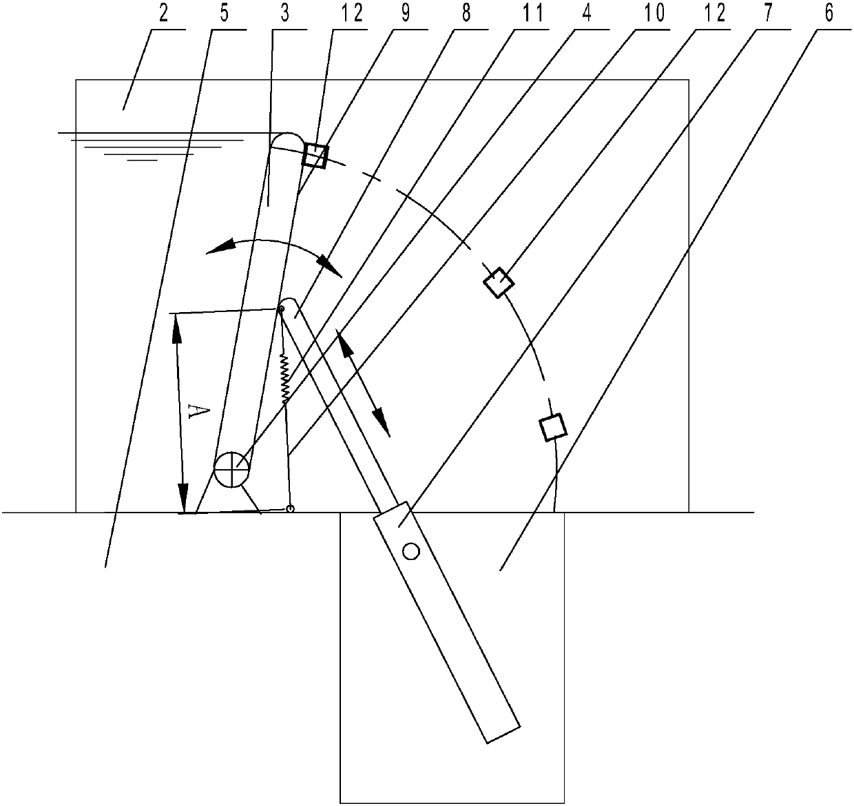
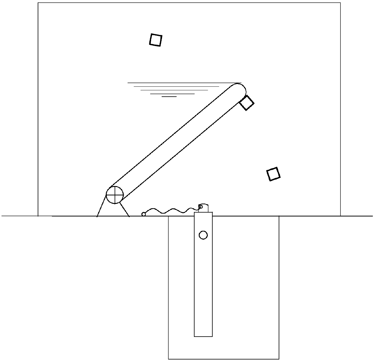
[0023] figure 1 , figure 2 It is a schematic diagram of a direct-push steel dam structure. It can be seen from the figure that it includes a steel dam door leaf 3 installed between the left wall 1 and the right side wall 2, and the bottom of the steel dam door leaf 3 is connected with the dam body 5 through the bottom horizontal shaft 4, and the steel dam door The leaf 3 swings around the bottom horizontal axis 4, and when the steel dam door leaf 3 swings up, it can block water, and when it swings down, it can discharge water. On the dam body 5 on the back surface of the steel dam door leaf 3, a plurality of pits 6 are formed in rows, and a lifting cylinder 7 is installed in the pit 6, and the front end of the piston rod 8 in the lifting cylinder 7 withstands the steel dam door leaf 3 The back 9 of the steel dam door leaf 3 is pushed up or ...


PUM


Abstract

The invention discloses a straight push type steel dam. The straight push type steel dam comprises a steel dam door leaf arranged between a left side wall and a right side wall. The straight push typesteel dam is characterized in that the bottom of the steel dam door leaf is connected with a dam body through a bottom cross shaft, and the steel dam door leaf swings around the bottom cross shaft; one or more pits in a row are formed in the position, on the air face of the steel dam door leaf, of the dam body; lifting oil cylinders are arranged in the pits, the front ends of piston rods in the lifting oil cylinders jack the back of the steel dam door leaf, the pistons stretch and shrink to push the steel dam door leaf to swing upwards or downwards, the front ends of the piston rods on the side close to the bottom cross shaft are connected with stay ropes, the other ends of the stay ropes are fixed to the positions, between the lifting oil cylinders and the bottom cross shaft, of the dambody, along with the stretching-out action of the piston rods, the piston rods are obliquely pulled by the stay ropes to one side of the steel dam door leaf, and the front ends of the piston rods always jack the steel dam door leaf; and limiting devices for applying multi-position positioning to the steel dam door leaf are arranged between the left side wall and the steel dam door leaf and betweenthe right side wall and the steel dam door leaf, the limiting devices are spring bolts stretching and shrinking laterally, and when the spring bolts stretch out, downward swinging of the steel dam door leaf is stopped.

Description

technical field [0001] The invention relates to a dam structure of water conservancy facilities, in particular to a direct push type steel dam. Background technique [0002] Steel dam gates are mechanical equipment in water conservancy and hydropower engineering facilities. It is mainly used in the construction of agricultural irrigation, fishery, ship locks, seawater tidal protection, urban river landscape engineering and small hydropower stations. The steel dam gate is a new type of gate that realizes the opening and closing of the steel dam gate through the rotation of the bottom horizontal axis driven by hydraulic equipment. It has the advantages of rapid opening and closing, and durability. It mainly includes the bottom horizontal shaft, the steel dam door leaf, the hoist installed in the lock chamber, etc. The two ends of the bottom horizontal shaft pass through the wall of the lock chamber to connect with the hoist, and rotate under the drive of the hoist. The botto...

Claims


Application Information

Patent Timeline
Patent Type & Authority Applications(China)
IPC IPC(8): E02B7/40E02B7/44E02B7/00
CPCE02B7/00E02B7/40E02B7/44
Inventor 徐诗根
Owner 浙江河好闸门科技有限公司
Why Eureka
Try Eureka