Driving scene transition prediction device and recommended driving operation display device for motor vehicle

a technology of driving scene and display device, which is applied in the direction of road vehicle traffic control, instruments, and variable traffic instructions, etc., can solve the problems of difficult timely delivery of effective information to the driver of the own motor vehicle, the device cannot use the previously predicted operation model of the traffic participants, and the large amount of calculation is difficult to achieve. , to achieve the effect of increasing the expression of symbols, reducing the amount of calculation, and ensuring the accuracy of prediction

Active Publication Date: 2012-06-21
DENSO CORP
View PDF4 Cites 12 Cited by
  • Summary
  • Abstract
  • Description
  • Claims
  • Application Information

AI Technical Summary

Benefits of technology

[0014]In the recommended driving operation display device equipped with the driving scene transition prediction device according to the exemplary embodiment, the symbolizing execution section symbolizes the entire of driving scene around the own motor vehicle. This makes it possible to obtain robustness in recognition and prediction of the driving scene. That is, even if the number of the traffic participants such as motor vehicles other than the own motor vehicle, pedestrians and traffic signals, it is possible to increase the expression of symbols only. Therefore it is not necessary to set operation models again and not necessary to execute the prediction when the number of the traffic participants is changed. On the other hand, it is necessary to execute the prediction again in the prior art techniques. The device according to the exemplary embodiment is adequately and flexibility applied to the increase and decrease of the number of traffic participants.
[0015]In the recommended driving operation display device equipped with the driving scene transition prediction device according to the exemplary embodiment, the prediction section predicts how the symbolized driving scene is transited in the candidates of operation to be executed by the own motor vehicle. At this time, the prediction section estimates the influence of the operation of the own motor vehicle to the operation of the traffic participants. The prediction section predicts the transition of the symbolized driving scene on the basis of the estimated interaction (or influence). Accordingly, it is possible for the device according to the exemplary embodiment to decrease a large amount of calculation when compared with the prior art techniques which use operation models which consider the interaction between each traffic participant and other traffic participants. Further, because the device according to the exemplary embodiment predicts the interaction (or influence) on the basis of the actual state change of each of the traffic participants, it is possible to increase the prediction accuracy of the transition of the driving scene.

Problems solved by technology

Because, the operation of the own motor vehicle is affected from the state of a traffic signal on a current road, a frame problem occurs when the device disclosed in the conventional patent document 1 is applied to a more usual driving scene where various traffic participants including traffic signals have a complex operation.
The frame problem is caused when an operation model such as a motor vehicle model is assigned to each of traffic participants and the entire operation of the traffic models is predicted on the basis of each of the operation models.
During the process of predicting a new operation model, it is impossible for the device to use the previously predicted operation model of the traffic participants, and difficult to timely provide effective information to the driver of the own motor vehicle.

Method used


Image

  • Driving scene transition prediction device and recommended driving operation display device for motor vehicle
  • Driving scene transition prediction device and recommended driving operation display device for motor vehicle
  • Driving scene transition prediction device and recommended driving operation display device for motor vehicle

Examples


Embodiment Construction

[0026]Hereinafter, various embodiments of the present invention will be described with reference to the accompanying drawings. In the following description of the various embodiments, like reference characters or numerals designate like or equivalent component parts throughout the several diagrams.

Exemplary Embodiment

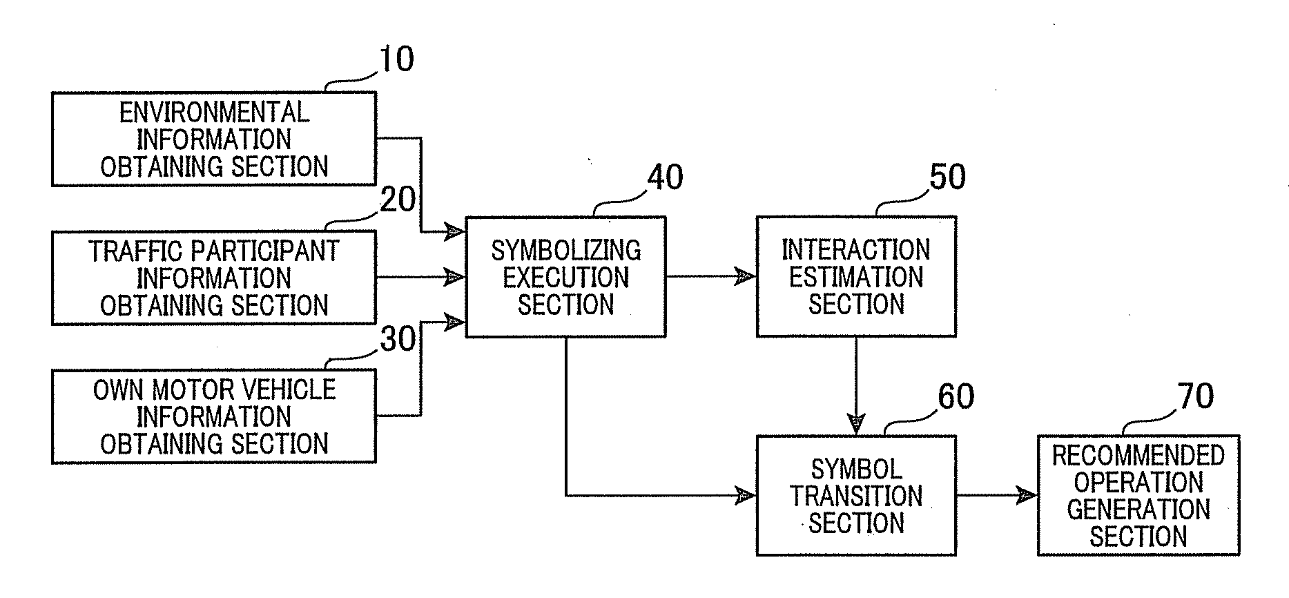
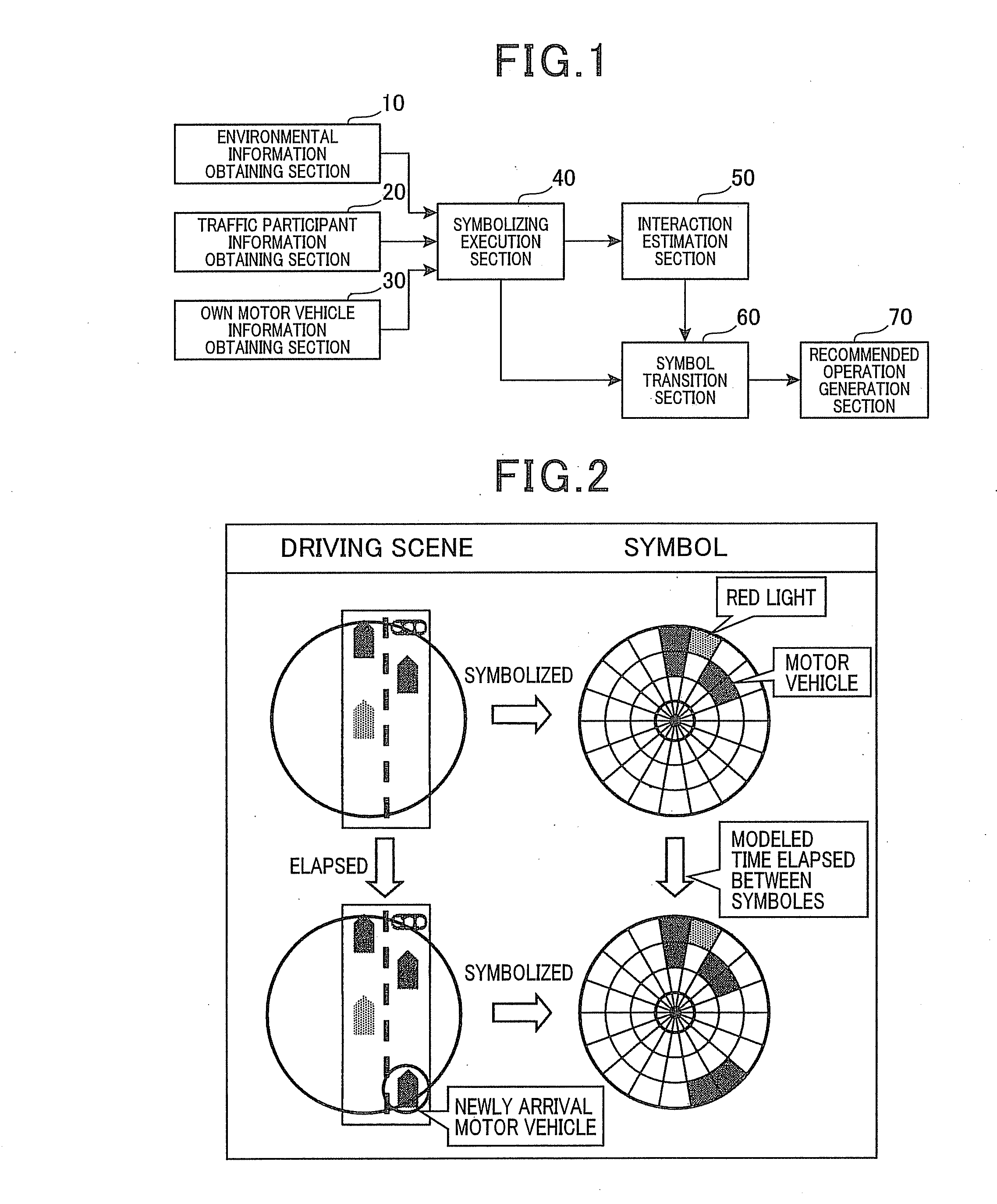
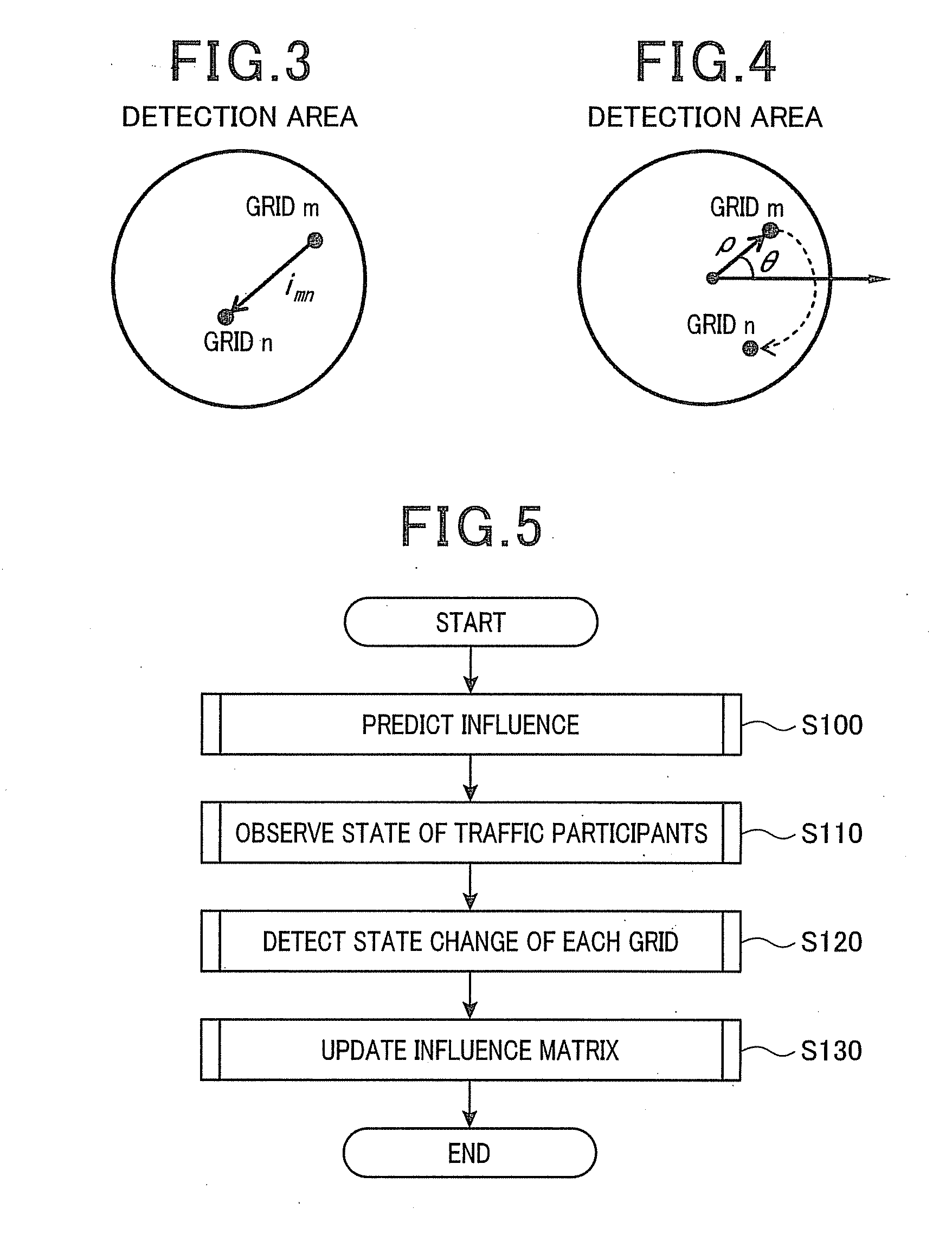
[0027]A description will be given of a recommended driving operation display device equipped with a driving scene transition prediction device according to an exemplary embodiment of the present invention with reference to FIG. 1 to FIG. 9.

[0028]FIG. 1 is a block view showing an entire structure of the recommended driving operation display device equipped with the driving scene transition prediction device for a motor vehicle according to the exemplary embodiment.

[0029]The recommended driving operation display device equipped with the driving scene transition prediction device is comprised of various types of sensors, a communication device and an electric control devic...


PUM


Abstract

A symbolizing execution section symbolizes information regarding driving scenes, and describes an entire driving scene around the location of an own motor vehicle. This makes it possible to only increase the information to be symbolized when the number of traffic participants is increased. This can adopt the increase of the traffic participants. A symbol transition prediction section predicts a transition of the symbolized driving scene by using influence which affects the operation of the traffic participants caused by the operation of the own motor vehicle. This makes it possible to increase prediction accuracy while decreasing a large amount of calculation on predicting the transition of driving scene.

Description

CROSS-REFERENCE TO RELATED APPLICATION[0001]This application is related to and claims priority from Japanese Patent Application No. 2010-282000 filed on Dec. 17, 2010, the contents of which are hereby incorporated by reference.BACKGROUND OF THE INVENTION[0002]1. Field of the Invention[0003]The present invention relates to driving scene transition prediction devices capable of predicting how a driving scene of a motor vehicle is transited to another driving scene in the future, and further relates to recommended driving operation display devices capable of supplying and displaying driving recommendation operation to the driver of the motor vehicle on the basis of the predicted driving scene.[0004]2. Description of the Related Art[0005]A conventional patent document 1, Japanese laid open publication No. 2003-228800, discloses a device for predicting future operation of motor vehicles which are present around an own motor vehicle. The device generates future operation of the own motor ...

Claims


Application Information

Patent Timeline
Patent Type & Authority Applications(United States)
IPC IPC(8): G08G1/09
CPCG08G1/164G08G1/167G08G1/166G08G1/165
Inventor BANDOU, TAKASHIMIYAHARA, TAKAYUKITAMATSU, YUKIMASA
Owner DENSO CORP
Why Eureka
Try Eureka