Electrical wiring device with protective features

a technology of electrical wiring and protective features, applied in contact testing/inspection, relays, instruments, etc., can solve problems such as series arc faults, potential lethal current, and ground faults, and achieve the effect of inexpensive detection

Inactive Publication Date: 2012-06-21
PASS SEYMOUR
View PDF3 Cites 50 Cited by
  • Summary
  • Abstract
  • Description
  • Claims
  • Application Information

AI Technical Summary

Benefits of technology

[0011]The present invention addresses the needs described above by providing a protective system that inexpensively detects both end of life conditions and miswire conditions in first and subsequent installations.

Problems solved by technology

A ground fault may occur, for example, by frayed or missing insulation on a hot conductor disposed somewhere in the load circuit.
This current is potentially lethal.
This type of fault occurs when there is damaged insulation between a hot conductor and an adjacent conductor (that is at a different potential).
A series arc fault occurs because a termination in the load circuit is loose.
One drawback to all prior art electrical devices is that they are subject to one or more end of life conditions.
An end-of-life condition refers to a failure that should render the device unusable or unsafe for use.
For example, some end of life conditions may make a protective device non-protective.
Another drawback to prior art protective devices relates to the fact that can be miswired during installation.
When reverse wired, some prior art GFCIs are not capable of protecting the face receptacles.
These have lessened the chances for miswiring but unfortunately some installers choose to ignore installation instruction sheets.
As a result, no power is provided to the downstream circuit or the face terminals.
The lack of power eventually induces the installer to correct the miswired condition.
While this approach may be successful for an initial GFCI installation, it may not be operative for subsequent reinstallations.
Protective devices that do include miswire detection for subsequent installations often include relatively expensive solutions to the problem.

Method used


Image

  • Electrical wiring device with protective features
  • Electrical wiring device with protective features
  • Electrical wiring device with protective features

Examples


Embodiment Construction

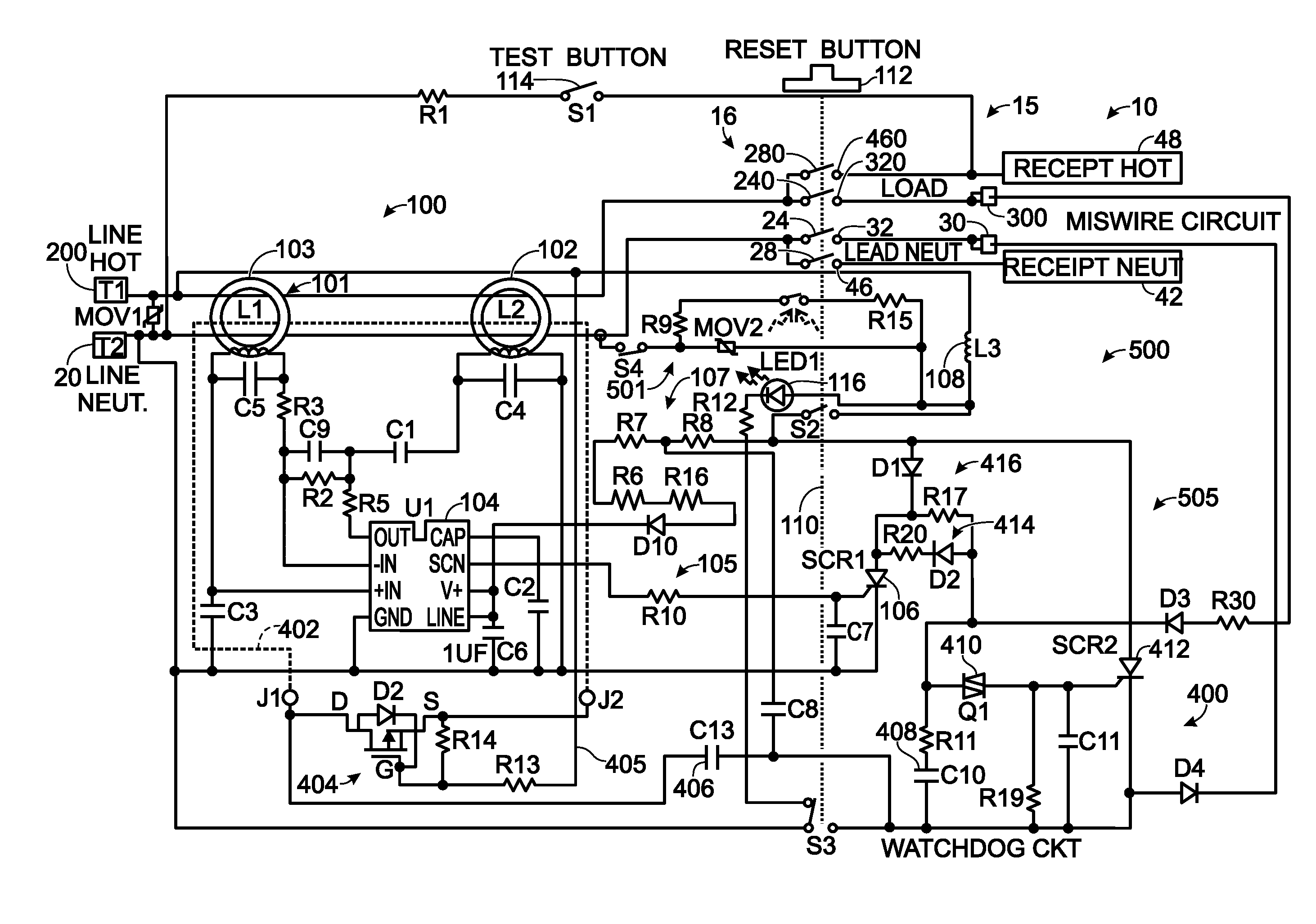
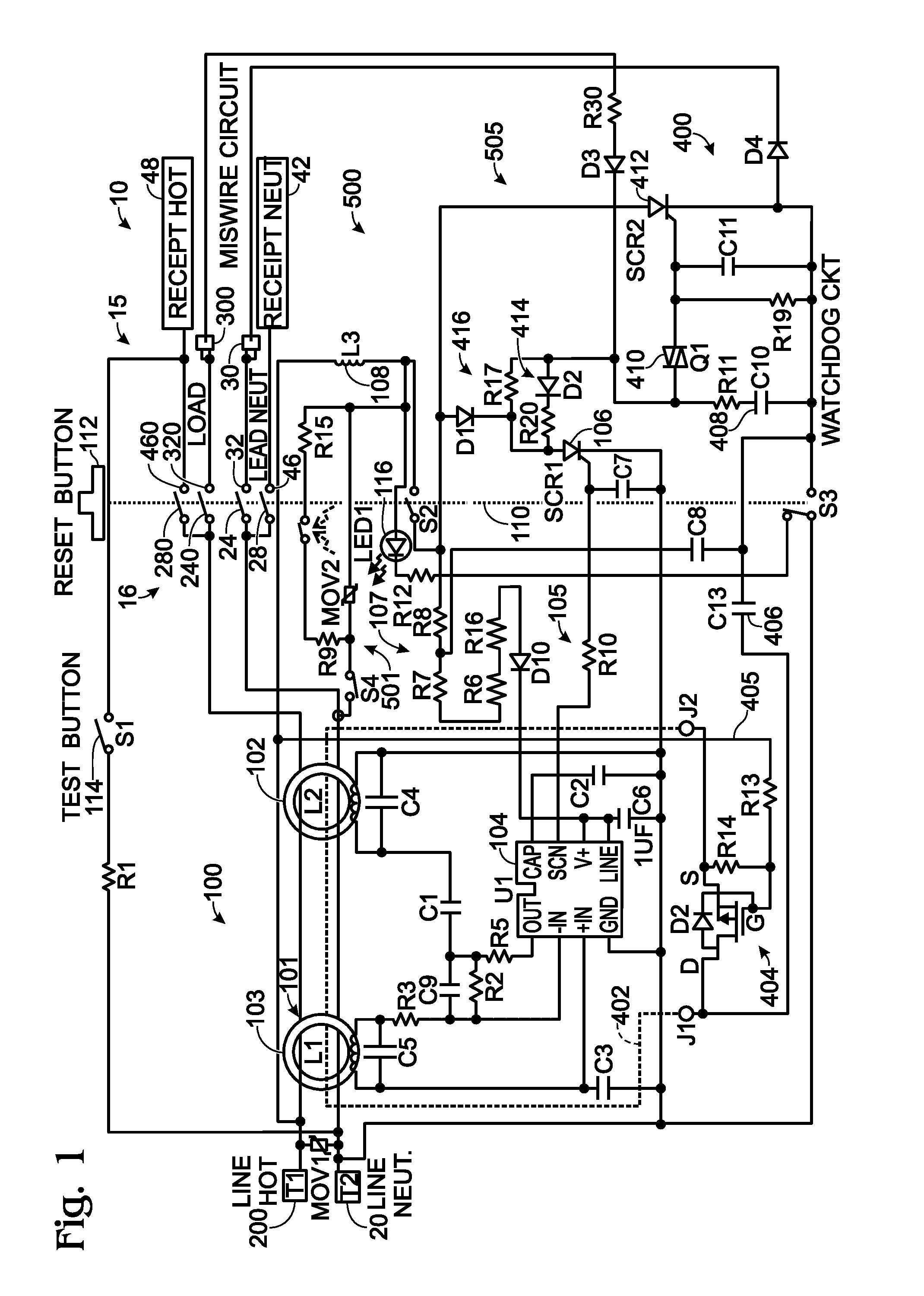
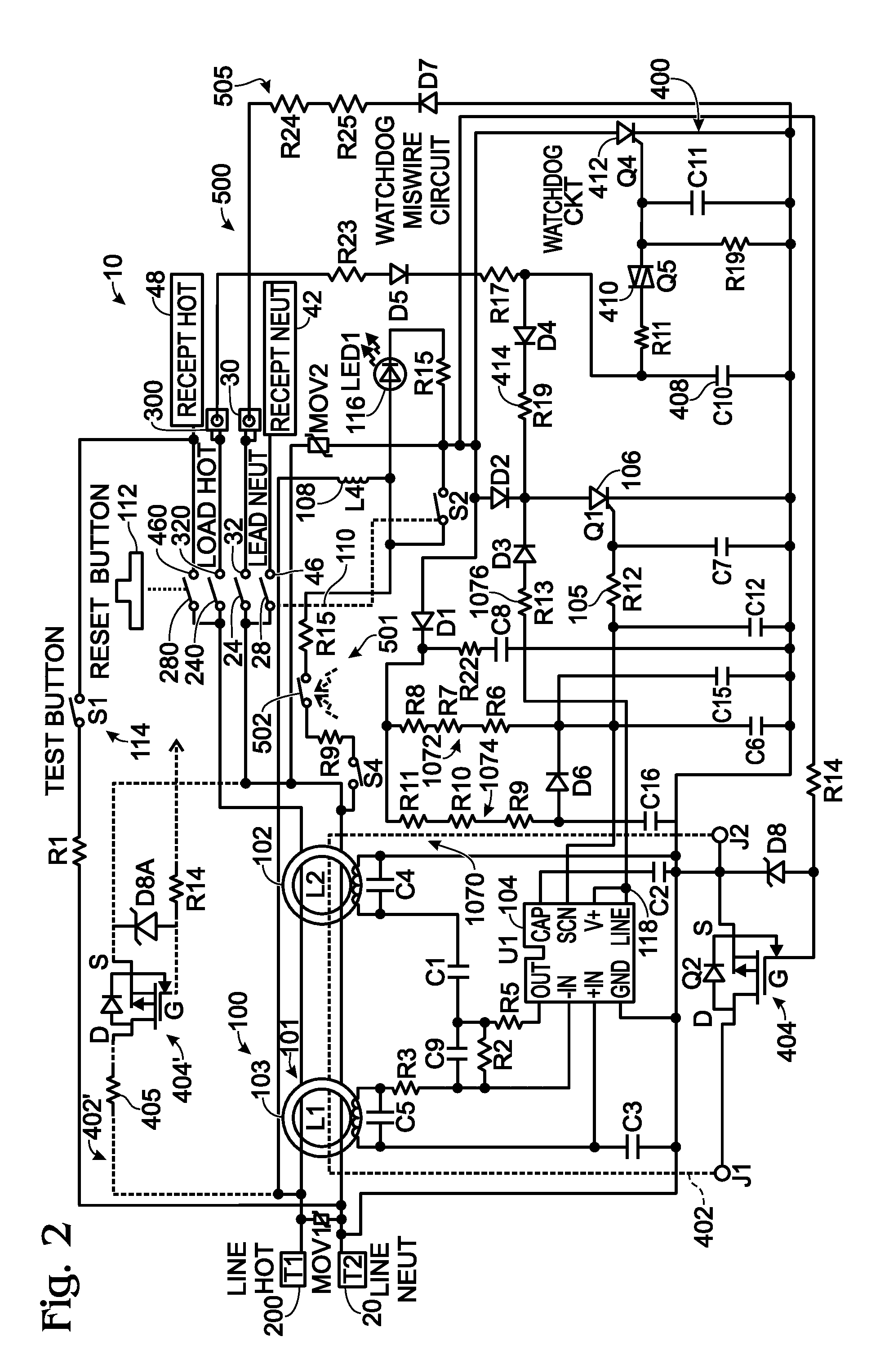
[0027]Reference will now be made in detail to the present exemplary embodiments of the invention, examples of which are illustrated in the accompanying drawings. Wherever possible, the same reference numbers will be used throughout the drawings to refer to the same or like parts. An exemplary embodiment of the protective device of the present invention is shown in FIG. 1, and is designated generally throughout by reference numeral 10.

[0028]As embodied herein and depicted in FIG. 1, a schematic diagram of a protective electrical device in accordance with a first embodiment of the present invention is disclosed. As an initial point, while FIG. 1 shows a GFCI embodiment, the teachings of the present invention are also applicable to AFCIs or other protective devices.

[0029]The protective electrical wiring device 10 includes a hot line terminal 200, neutral line terminal 20, hot load terminal 300, neutral load terminal 30, hot receptacle terminal 48 and neutral receptacle 42. The protecti...


PUM


Abstract

The present invention is directed to an electrical wiring device for use in an electrical distribution system. The device includes a plurality of line terminals configured to terminate the plurality of line conductors and a plurality of load terminals configured to terminate the plurality of load conductors. The protective circuit assembly includes at least one fault detector configured to generate a fault detection signal based on electrical perturbations propagating on at least one of the plurality of line terminals or at least one of the plurality of load terminals. A device integrity evaluation circuit includes a timing circuit coupled to the source of AC power by way of the plurality of load terminals and configured to generate a time measurement. The device integrity evaluation circuit is configured to reset the time measurement if the protective circuit assembly generates the fault detection signal during a predetermined test interval in the properly wired condition. The device integrity evaluation circuit is configured to generate a device integrity fault signal when the time measurement exceeds a predetermined threshold. A circuit interrupter assembly includes movable contacts configured to be latched into a reset state in response to a reset stimulus. The movable contacts are configured to be driven into a tripped state in response to the fault detection signal or the device integrity fault signal.

Description

BACKGROUND OF THE INVENTION[0001]1. Field of the Invention[0002]The present invention relates generally to electrical wiring devices, and particularly to electrical wiring devices having protective features.[0003]2. Technical Background[0004]An electric distribution system transmits AC power from a breaker box to one or more load circuits disposed in a structure to provide electrical power throughout. A load circuit may include any number of electrical devices such as electrical outlets, lighting devices, appliances, or other such devices. An electric circuit typically includes at least one protection device. Examples of electric circuit protection devices include ground fault circuit interrupters (GFCIs), arc fault circuit interrupters (AFCIs), or devices that include both GFCIs and AFCIs in one protective device.[0005]A protective device is mounted in an upstream outlet box within the electric circuit and non-protective devices, such as receptacles, are mounted downstream of the p...

Claims


Application Information

Patent Timeline
Patent Type & Authority Applications(United States)
IPC IPC(8): H01H47/22G01R31/55
CPCH01H47/22H02H3/162G01R31/025H02H3/335G01R31/55H01H1/0015H01H83/04
Inventor MCMAHON, MICHAELMORGAN, KENT R.
Owner PASS SEYMOUR
Why Eureka
Try Eureka