Radar system mounted on vehicle

a technology of radar system and vehicle, which is applied in the direction of measuring devices, using reradiation, instruments, etc., can solve the problems of vehicle control system or alarm system failure, detection error may occur, detection failure, etc., and achieve high performance, reliable detection of interference wave reception, and low cost

Inactive Publication Date: 2005-05-17
MITSUBISHI ELECTRIC CORP
View PDF11 Cites 16 Cited by
  • Summary
  • Abstract
  • Description
  • Claims
  • Application Information

AI Technical Summary

Benefits of technology

[0008]The present invention has been made to solve the above-mentioned problems, and therefore an object of the present invention is to provide a radar system mounted on a vehicle which reliably detects the reception of the interference wave with high performance and inexpensively.
[0009]With the above object in view, a radar system of the present invention mounted on a vehicle for detecting a target object comprises a transmitting means for transmitting an electromagnetic wave and a receiving means for receiving the electromagnetic wave reflected by the target object. The radar system also comprises a signal processing means for measuring a distance between a vehicle of his / her own and the target object and a relative velocity on the basis of the transmitting electromagnetic wave and the receiving electromagnetic wave. The system further comprises an interference detecting means for suspending a transmit operation of the transmitting means under a control of the signal processing means to detect an interference signal from an other external device. With this structure, upon detecting the interference, since only the receive operation is conducted without conducting the transmit operation, only the interface wave entering into the radar can be reliably measured without measuring the reflection wave of an obstacle on a road, to thereby improve the reliability of the interference detection. Also, since the interference detection can be implemented only by the radar signal processing without adding the special hardware (H / W) for detection of the interference, an inexpensive radar system mounted on the vehicle can be realized with high performance.

Problems solved by technology

However, the above-mentioned conventional general radar system mounted on the vehicle has an S / N ratio deteriorated upon receiving an interference wave of another radio device or another automobile radar, resulting in a case in which detection may be in failure or a detection error may occur.
Thus, there arises such a problem that a vehicle control system or an alarm system fails.
Therefore, in the case where the car-to-car distance measuring device receives an interference pulse before receiving a reflection light from the target after transmitting the pulse light, there arises such a problem that a receive light level is relatively constant and large and a distance value is inaccurate.
However, because the radar using an electric wave and the radar using the light are different from each other in a principle for detecting the reflection wave, Japanese Patent No. 03185547 arises such a problem that the electric wave type radar does not function accurately.
Also, in the case of the radar using the electric wave, there arises such a problem that the interface wave input within an observation time reliably induces deterioration of detection performance or detection error.

Method used


Image

  • Radar system mounted on vehicle
  • Radar system mounted on vehicle
  • Radar system mounted on vehicle

Examples


first embodiment

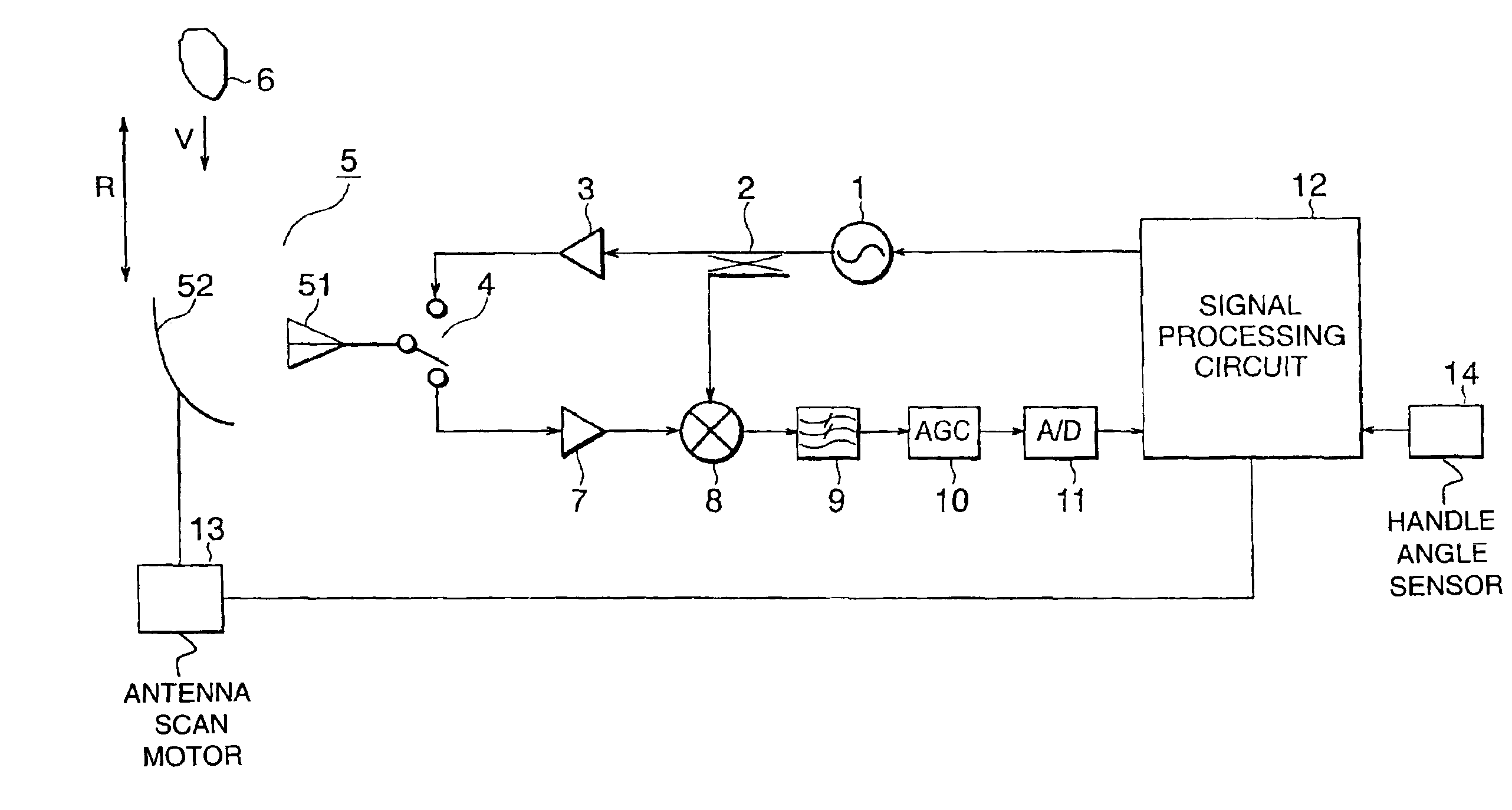
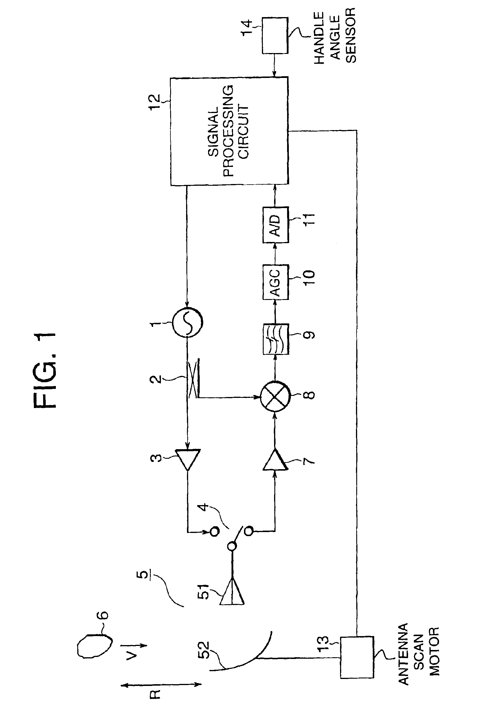
[0023]FIG. 1 is a block diagram showing a structure of a radar system mounted on a vehicle in accordance with the present invention. An example shown in FIG. 1 also uses a transmit / receive shared antenna. As shown in FIG. 1, a power divider 2 is located so as to input an electromagnetic wave outputted from an oscillator 1. The electromagnetic wave is divided into two waves by the power divider 2, one of which is input to a transmitting amplifier 3 and the other of which is input to a mixer 8. Downstream of the transmitting amplifier 3 is located an antenna 5 composed of a primary radiator 51 and a reflector antenna 52 through a transmit / receive changeover switch 4. Also, there is disposed a receive amplifier 7 for inputting the electromagnetic wave reflected by the target object 6 and received by the antenna 5, and an output from the receive amplifier 7 is input to the above-mentioned mixer 8. Downstream of the mixer 8 are disposed a filter 9, an AGC amplifier 10, and an AD converte...

second embodiment

[0045]A method of judging whether or not the interference wave is observed, in Step S500 in the first embodiment will be hereinbelow described as a second embodiment. A transmit wave from another radar uses various modulation systems, and a probability that a transmitting frequency, a modulation timing, a receive timing or the like completely coincides with each other is very low. In this case, since there is no correlation when the interference wave is received, the spectrum of the interference wave signal cannot be reproduced by FFT, and a noise floor increases as a white noise as indicated by the FFT results shown in FIG. 7. In FIG. 7, reference numeral 30 denotes a noise floor at the time of receiving the interference wave, reference numeral 31 is a given threshold level for interference detection, and reference numeral 32 is a heat noise. In the case where a threshold level for detection of the interference wave which is given times of the noise floor level at the time of recei...

third embodiment

[0048]Another method of judging whether or not the interference wave is observed in Step S500 in the first embodiment will be hereinbelow described as a third embodiment. There is a case in which the transmitting frequency, the modulation timing, the receive timing or the like completely coincide with each other in the interference from the radar of the same modulation system. In this case, since the correlation coincides with each other, there is a case in which the interference wave is reproduced as the normal signal spectrum by FFT. In this case, in the case where a threshold level for detection of the interference wave which is given times of the noise floor level at the time of receiving no interference wave is predetermined as shown in FIG. 8, and a peak level of the reproduced spectrum becomes higher than the threshold level, it is judged that the interference wave is received. In FIG. 8, reference numeral 40 denotes a spectrum noise floor at the time of receiving the interfe...


PUM


Abstract

To provide a radar system mounted on a vehicle that reliably detects the reception of the interference wave with high-performance and inexpensively. There is provided a radar system mounted on a vehicle for detecting a target object, including a transmitter for transmitting an electromagnetic wave, a receiver for receiving the electromagnetic wave reflected by the target object, a signal processor for measuring a distance between a vehicle of his / her own and the target object and a relative velocity on the basis of the transmitting electromagnetic wave and the receiving electromagnetic wave, and an interference detector for suspending a transmit operation of the transmitter under a control of the signal processor to detect an interference signal from another external device.

Description

BACKGROUND OF THE INVENTION[0001]1. Field of the Invention[0002]The present invention relates to a radar system mounted on a vehicle, and more particularly to a radar system mounted on a vehicle such as an automobile and used for measurement of a distance between vehicles.[0003]2. Description of the Related Art[0004]As such a general radar system mounted on the vehicle, there have been known many radar systems which are downsized by using a transmit / receive shared antenna and improves in the mounting property of a subject automobile. In the radar system of this type, an electromagnetic wave of a frequency of, for example, a transmitting frequency ftx=76.5 GHz is outputted from an oscillator, and the electromagnetic wave is allowed to pass through a power divider and amplified by a transmitting antenna. The electromagnetic wave amplified by the transmitting amplifier is allowed to pass through a transmit / receive changeover switch and is outputted to a space from the transmit / receive ...

Claims


Application Information

Patent Timeline
Patent Type & Authority Patents(United States)
IPC IPC(8): G01S7/36G01S13/34G01S13/02G01S13/93G01S13/00G01S7/02G08G1/16G01S7/28G01S13/931
CPCG01S7/023G01S7/36G01S7/021G01S2013/9325G01S13/345G01S13/931
Inventor UEHARA, NAOHISAKAI, KOICHI
Owner MITSUBISHI ELECTRIC CORP
Why Eureka
Try Eureka