Thin film capacitors

a thin film capacitor and film capacitor technology, applied in the field of capacitors, can solve the problems of premature breakdown, excessive localized thermal stress, and limited high frequency quality factor of such capacitors

Active Publication Date: 2012-06-21
NXP USA INC
View PDF4 Cites 59 Cited by
  • Summary
  • Abstract
  • Description
  • Claims
  • Application Information

AI Technical Summary

Problems solved by technology

The losses in the thin bottom electrodes can limit the overall high frequency quality factor of such capacitors.
Additionally, the higher electrical field between the top and bottom electrodes at the edge of the crossover can create premature breakdown under the application of high bias voltages or large AC signals to the capacitor.
As the frequency increases, electromagnetic waves travel towards the surface of the circuits, making the surface properties, deposition techniques and design critical.
Such failures may be caused either by direct thermal loads or by electrical resistive loads, which in turn generate excessive localized thermal stresses.
Depending on the magnitude of the applied stress and its duration, the deformation may become so large that it will experience brittle and / or ductile fracture, interfacial separation and creep rupture.
High-frequency device losses consist of material-related losses in the film and at the electrode-film interface, as well as the resistive losses in the electrodes.
This interface is generally the cause of losses at high frequencies and premature breakdown at low voltages.
Also, the designs on current devices are limited by traditional design guidelines that create resistive losses due to design constraints.

Method used


Image

  • Thin film capacitors
  • Thin film capacitors
  • Thin film capacitors

Examples


Embodiment Construction

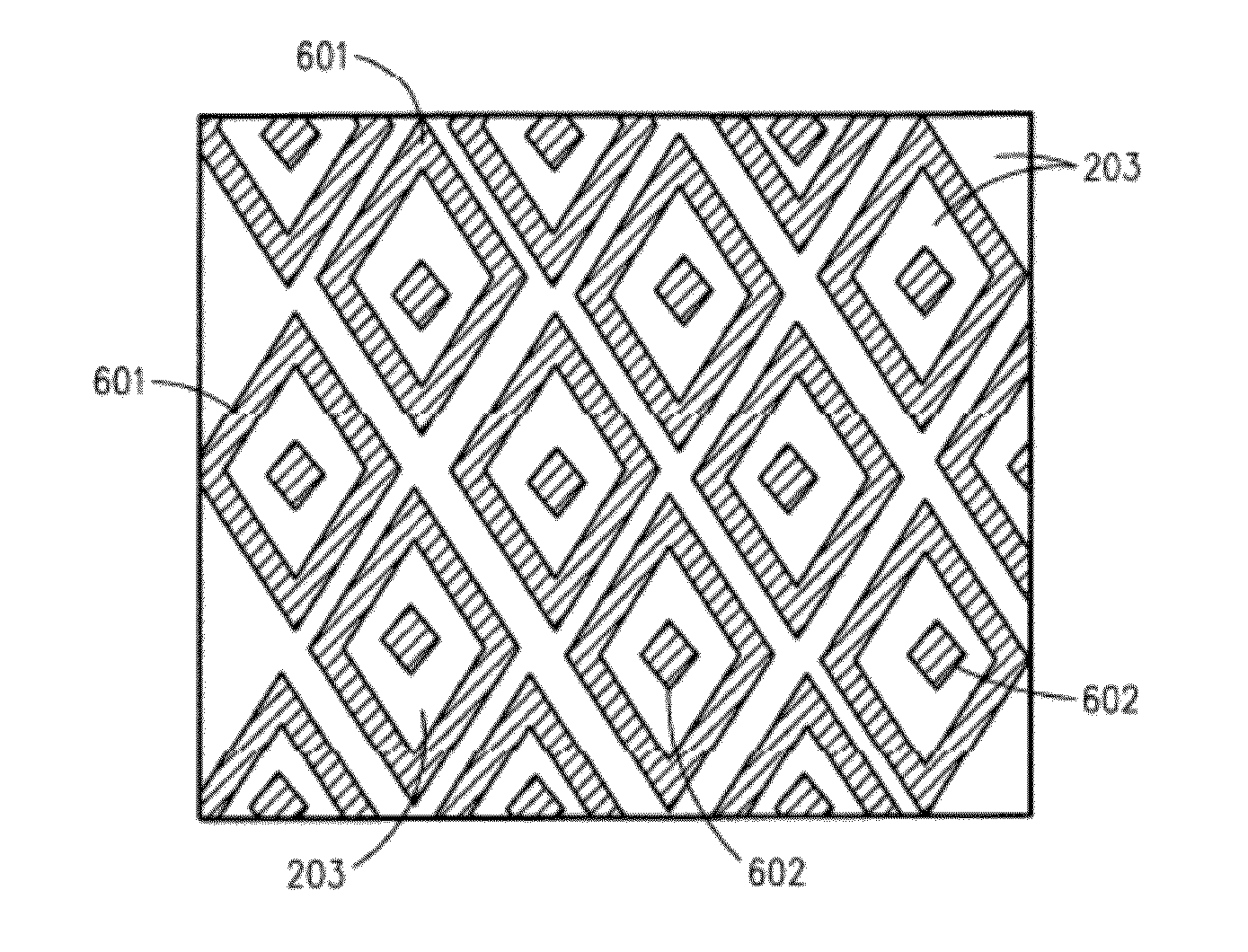
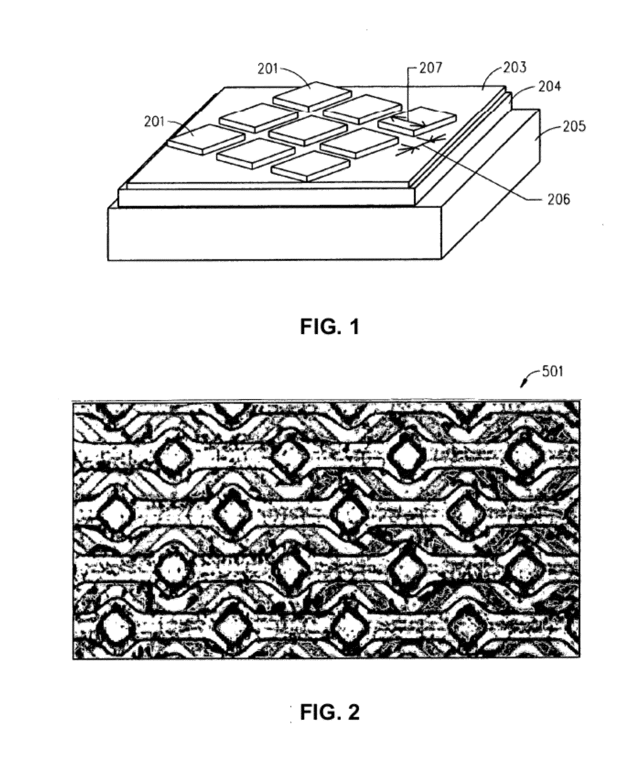
[0020]The present disclosure describes, among other things, illustrative embodiments of systems and methods for providing tunable capacitors, such as BST thin film capacitors, where there is reduced contact with the bottom electrodes and which creates an improved periphery with an improved quality (Q) factor and a desired aspect ratio range.

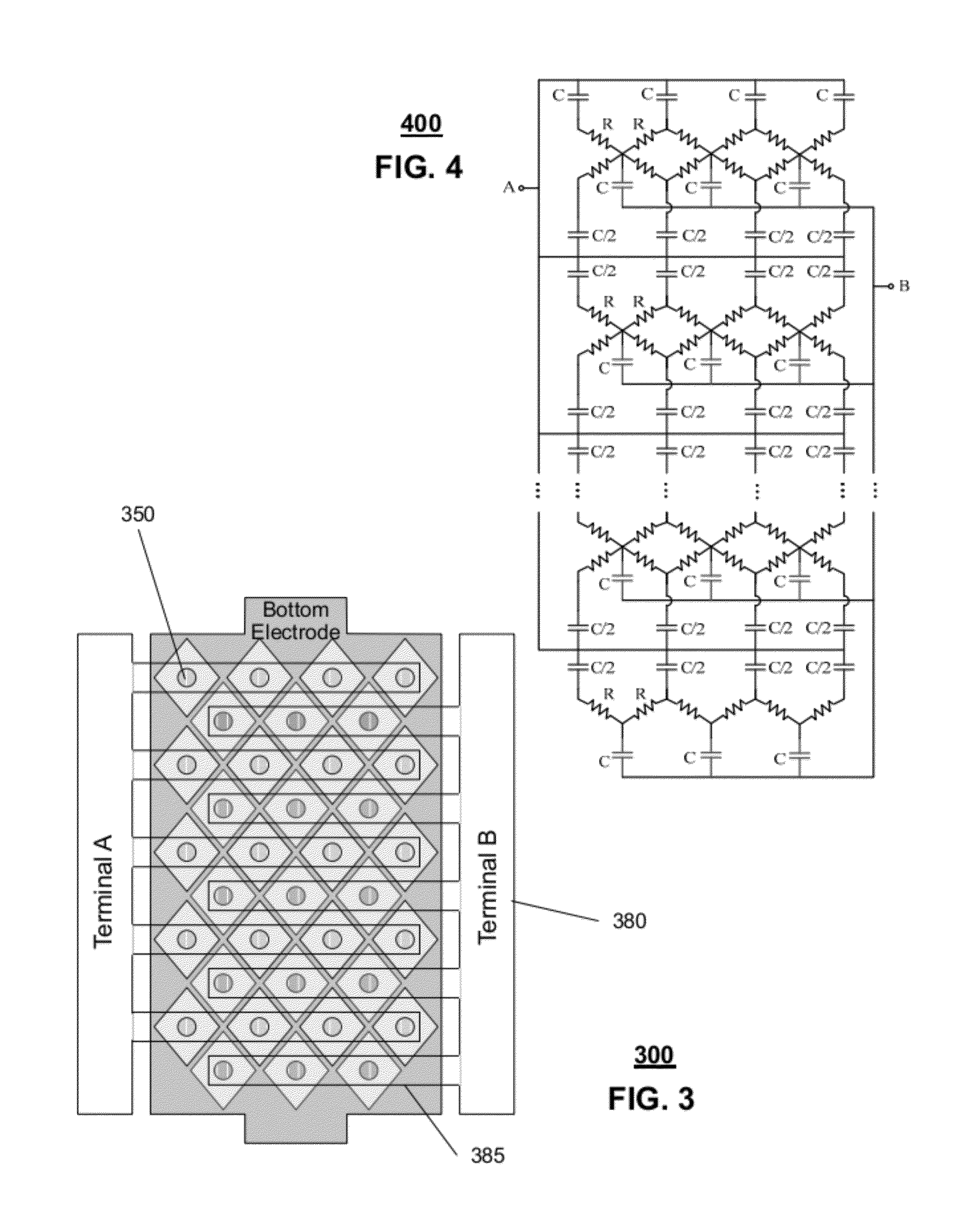
[0021]One embodiment of the present disclosure can include an apparatus having a first solid electrode, a second electrode separated into subsections, and a dielectric medium separating the subsections from the first solid electrode. The subsections of the second electrode can include a first group of subsections and a second group of subsections. The first group of subsections and the first solid electrode can form a first group of capacitors. The second group of subsections and the first solid electrode can form a second group of capacitors. Each capacitor of the first group of capacitors can be in parallel. Each capacitor of the second group o...


PUM


Abstract

A system that incorporates teachings of the present disclosure may include, for example, a first solid electrode, a second electrode separated into subsections, and a dielectric medium separating the subsections from the first solid electrode, where the subsections of the second electrode include a first group of subsections and a second group of subsections, where the first group of subsections are connectable with a first terminal for receiving an input signal, and where the second group of subsections is connectable with a second terminal for providing an output signal. Other embodiments are disclosed.

Description

CROSS REFERENCE TO RELATED APPLICATIONS[0001]This application is a continuation-in-part of application Ser. No. 11 / 602,114 filed Nov. 20, 2006, which was a continuation-in-part of application Ser. No. 10 / 938,898 filed Sep. 10, 2004, which was a continuation of application Ser. No. 10 / 455,901 filed Jun. 6, 2003 now U.S. Pat. No. 6,864,757, which was a divisional of application Ser. No. 09 / 909,187 filed Jul. 19, 2001 now U.S. Pat. No. 6,590,468, which claimed priority to US provisional application No. 60 / 219,500 filed Jul. 20, 2000. The disclosures of each of these applications are hereby incorporated by reference herein in their entirety. This application is also a continuation-in-part of application Ser. No. 12 / 321,897 filed Jan. 27, 2009, which was a divisional of application Ser. No. 11 / 598,354 filed on Nov. 13, 2006 now U.S. Pat. No. 7,869,186, which claimed priority to US provisional application No. 60 / 736,366 filed Nov. 14, 2005. The disclosures of each of these applications ar...

Claims


Application Information

Patent Timeline
Patent Type & Authority Applications(United States)
IPC IPC(8): H01G4/30H01G4/005
CPCH01G4/33H01G4/38H04B1/0458H03H2001/0014H01G7/06
Inventor OAKES, JAMESMARTIN, JAMESHORNE, EDWARD PROVO WALLISMCKINZIE, WILLIAM E.
Owner NXP USA INC
Why Eureka
Try Eureka