Light Emitting Diode Retrofit Kit For High Intensity Discharge Lighting

a technology of light emitting diodes and retrofit kits, which is applied in the field of high intensity discharge lighting and light emitting diodes lighting, can solve the problems of low light efficiency, low light efficiency, and low light efficiency of hid luminaires over the useful life of hid luminaires, and achieves the effects of reducing the life of led products, reducing maintenance costs and energy waste, and reducing energy consumption

Inactive Publication Date: 2012-06-21
LED IND
View PDF2 Cites 41 Cited by
  • Summary
  • Abstract
  • Description
  • Claims
  • Application Information

AI Technical Summary

Benefits of technology

[0013]With the method accomplished, the retrofit high intensity discharge lighting fixture is no longer a source of high intensity discharge light and is instead a source of light emitting diode light, and also the at least one light emitting diode light source, being outside the light emitting diode lighting fixture chamber, is substantially free of exposure to the temperature effects of being within either the high intensity discharge lighting fixture chamber of the light emitting diode lighting fixture chamber.

Problems solved by technology

The HID (High Intensity Discharge) exterior lighting industry has suffered from energy inefficiencies and light degradation over the useful life of an HID luminaire.
The result has been high maintenance costs and energy waste.
The LED has two weaknesses: 1—heat (the TJ junction has a temperature determined by the manufacturer of the LED product, that should not be exceeded or the life hours of the LED product will diminish) and, 2—excessive drive current (the higher the drive current the shorter the life of the LED product, the lower the drive current the longer the life of the LED product).

Method used


Image

  • Light Emitting Diode Retrofit Kit For High Intensity Discharge Lighting
  • Light Emitting Diode Retrofit Kit For High Intensity Discharge Lighting
  • Light Emitting Diode Retrofit Kit For High Intensity Discharge Lighting

Examples


Embodiment Construction

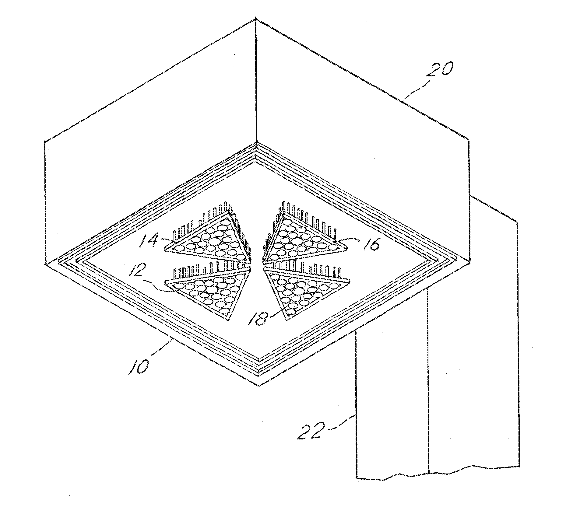
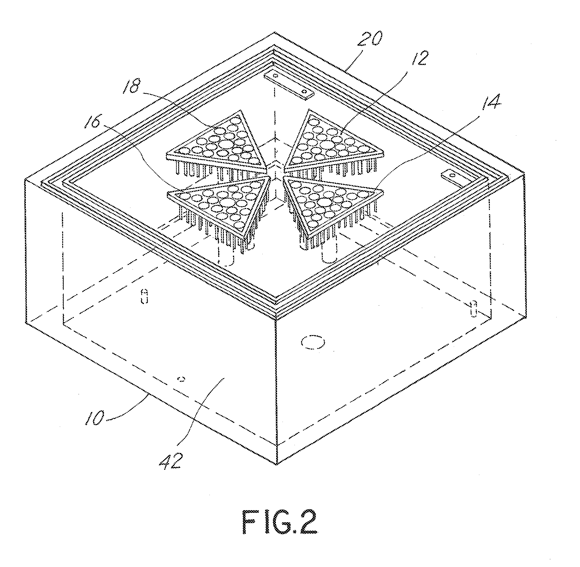
[0024]Referring to FIG. 1, the invented retrofit kit 10 may appear in public in part in the form of multiple modules, as for example with four modules 12, 14, 16, 18, visible below an original housing 20 atop a light pole or post 22.

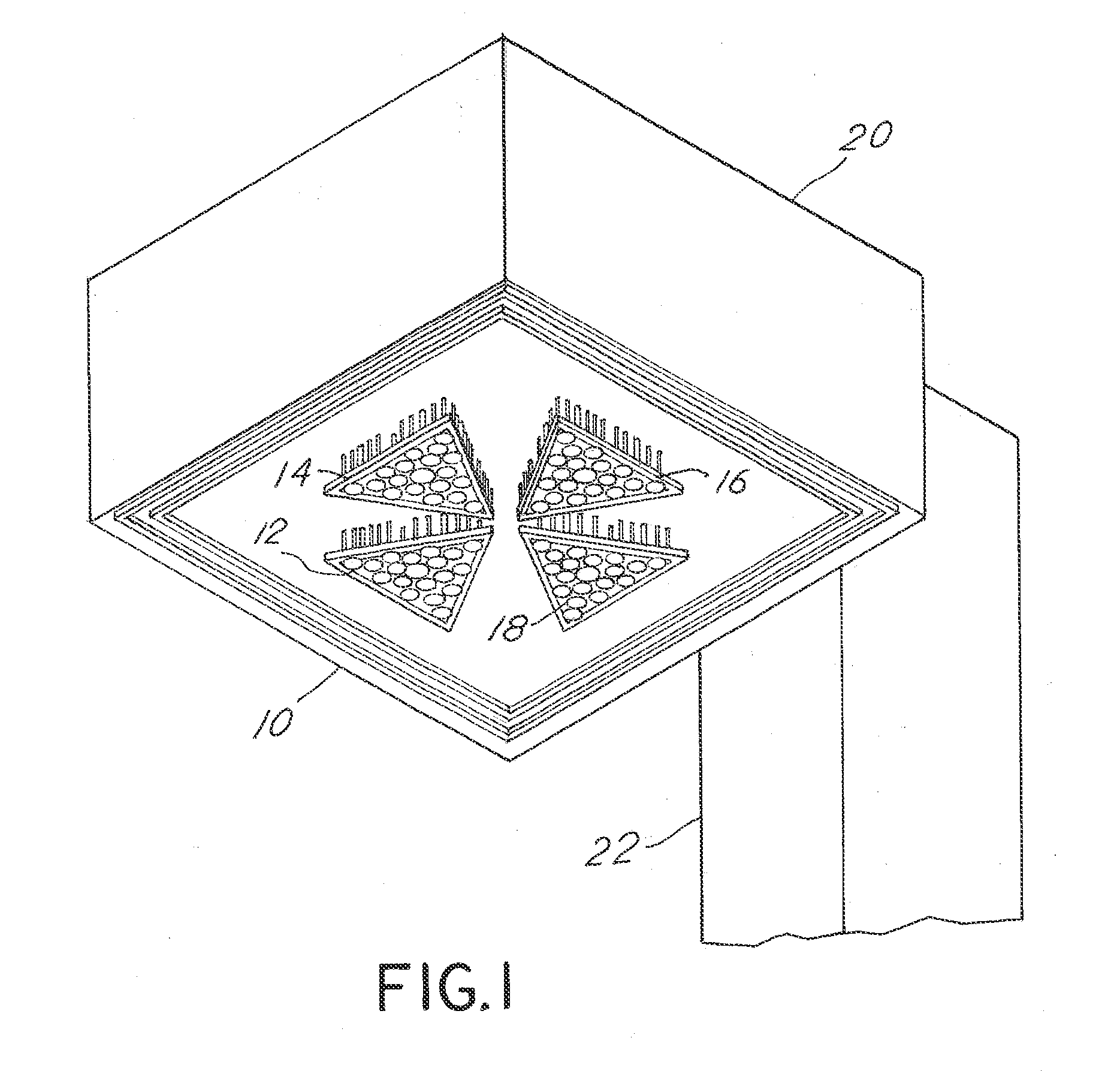
[0025]Referring to FIG. 2, the kit 10 is shown on a workbench. The modules 12, 14, 16, 18 of the invented retrofit kit can be constructed in different shapes and sizes. An example as in the accompanying FIGS. 2 and 4 would be the following: a 4 inch isosceles triangle marked as an anodized heat sink 24 with fifteen LEDs such as LED 26 and a microprocessor (not shown). Beginning with a heat sink 24 of that size and shape, the light emitting diodes such as diode 26 are mounted and anodized to the flat surface 28 of the heat sink 24 for maximum heat dissipation. Other electronics such as the microprocessor are also mounted to the flat surface 28 of the heat sink allowing for greater control of the completed module 12.

[0026]Each LED 26 of the module 12 is on...


PUM

PropertyMeasurementUnit
diameteraaaaaaaaaa
lengthaaaaaaaaaa
temperatureaaaaaaaaaa

Abstract

A housing once included a high intensity discharge (HID) light source, lens, and fixture chamber between the housing and lens. The housing is retrofit to exclude a routinely functioning HID light source and exclude at least a portion of the HID lens. The housing is made to include at least a first support for at least one light emitting diode (LED) light source and an LED diode lighting fixture chamber. A second support is affixed at least to the first support and is positioned at least in part outside the LED fixture chamber. The LED light source is mounted to the second support outside the LED fixture chamber. At least one LED light source lens is mounted to provide a lens for the LED light source, also outside the LED lighting fixture chamber. The LED light source is thereby substantially free of exposure to the temperature effects.

Description

CROSS-REFERENCE TO RELATED APPLICATIONS[0001]This application claims the benefit of provisional patent application No. 61 / 424,154 filed on Dec. 17, 2010.BACKGROUND OF THE APPLICATION[0002]This invention relates to lighting, including high intensity discharge lighting and light emitting diode lighting.[0003]The HID (High Intensity Discharge) exterior lighting industry has suffered from energy inefficiencies and light degradation over the useful life of an HID luminaire. The result has been high maintenance costs and energy waste. The Light Emitting Diode (LED) stands as one of the possible answers if engineered correctly.[0004]The LED has two weaknesses: 1—heat (the TJ junction has a temperature determined by the manufacturer of the LED product, that should not be exceeded or the life hours of the LED product will diminish) and, 2—excessive drive current (the higher the drive current the shorter the life of the LED product, the lower the drive current the longer the life of the LED p...

Claims


Application Information

Patent Timeline
Patent Type & Authority Applications(United States)
IPC IPC(8): F21V5/04B23P17/04F21V31/00F21V21/00F21V29/00
CPCF21K9/30F21V19/0055F21V31/005Y10T29/49716Y10S362/80F21V29/80F21V29/81F21Y2101/02F21V5/04F21V23/006F21V29/77F21K9/20F21K9/69F21Y2115/10Y10T29/49117F21V17/12F21V23/001F21V29/83
Inventor SCHUPPLE, JAMES WILLISHENRIE, JOSEPH BRIAN
Owner LED IND
Why Eureka
Try Eureka