Piezo valve

a valve and piezo technology, applied in the direction of valve details, valve arrangement, thin material handling, etc., can solve the problems of conventional piezo valves, difficult to fasten piezo plates, and inability to adjust the fastening position of piezo plates, etc., and achieve the effect of easy production

Inactive Publication Date: 2012-06-28
INZICONTROLS
View PDF13 Cites 6 Cited by
  • Summary
  • Abstract
  • Description
  • Claims
  • Application Information

AI Technical Summary

Benefits of technology

[0014]Further, the present invention is intended to propose a piezo valve, which can distribute a force applied to an end of the piezo plate or can concentrate the force on one position.
[0052]Further, when both the insulating stick and the shift part are formed with the piezo plate by an insert molding process, the piezo plate can be easily produced in the form of an integrated module.

Problems solved by technology

However, because the piezo plate 7 of the piezo valve is fastened to the casing 2 at the second end thereof using the rubber plate 8 or the epoxy mixed with the hardening agent, it is very difficult to fasten the piezo plate 7 to the casing and it is impossible to adjust the fastened position of the piezo plate 7.
Further, because the first end of the piezo plate 7 directly opens or closes the valve seats 4A and 5A, the conventional piezo valve is problematic in that it has low sealing effect and low precision.
However, in the piezo valve, the rubber valve disc is directly attached to the first end of the piezo plate 7 using the bonding agent, so that the properties of the bending-strained end of the piezo plate 7 may be reduced or the end of the piezo plate 7 may be twisted, thereby reducing the valve performance of the piezo valve or reducing the precision of the piezo valve.
However, the piezo valve is problematic in that a fluid passes both by the circuit board and by the pressure sensor, and that the fluid shortens the life spans of the circuit board and the pressure sensor and the piezo valve cannot realize precise control of the flow of a liquid fluid.

Method used


Image

  • Piezo valve
  • Piezo valve
  • Piezo valve

Examples


Embodiment Construction

[0062]Hereinbelow, a piezo valve according to an embodiment of the present invention will be described with reference to the accompanying drawing.

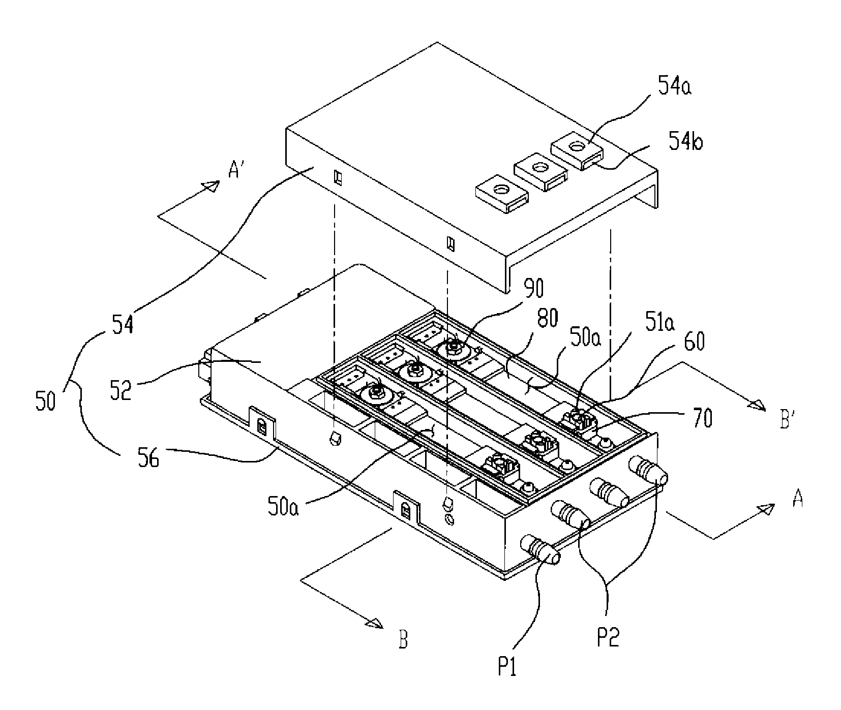
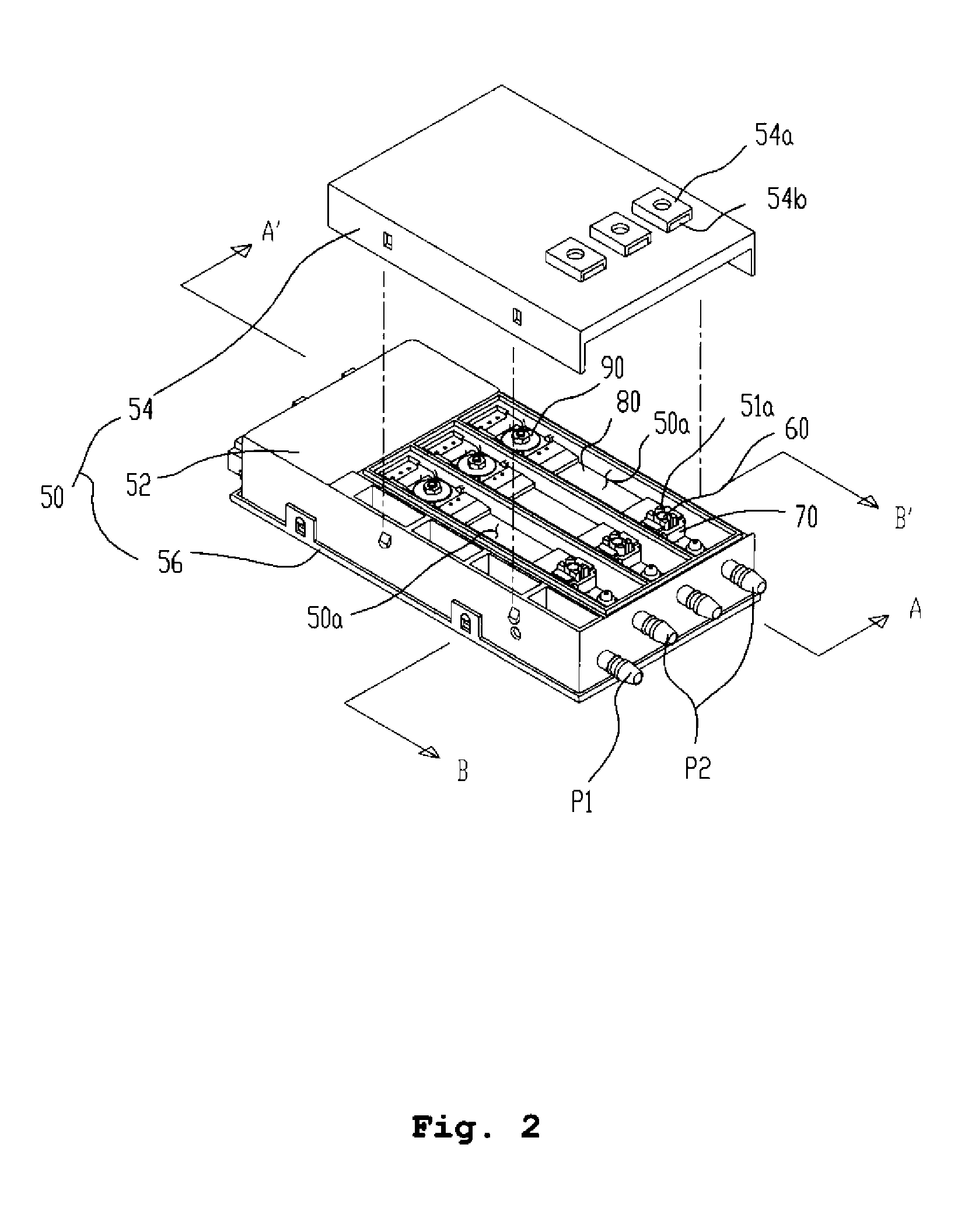
[0063]As shown in FIG. 2, the piezo valve according to an embodiment of the present invention includes a valve body 50 having separate parts, a valve unit 60, a piezo plate 80 and a fastener 90.

[0064]The valve body 50 may comprise a casing 52, a first cover 54 and a second cover 56, as shown in the drawing.

[0065]An internal chamber 50a is defined in the casing 52, as shown in the drawing. The casing 52 is open at an end thereof, as shown in the drawing, so that the internal chamber 50a is exposed to the atmosphere. The casing 52 may have a plurality of internal chambers 50a, as shown in the drawing, or may have a single internal chamber unlike the embodiment shown in the drawing. When the plurality of internal chambers 50a is defined in the casing, it is preferable that the chambers be defined in the form of a continuous parallel arrangeme...


PUM


Abstract

A piezo valve actuated by an electric voltage. The piezo valve includes a valve body having at least one port for introducing a fluid therethrough, an internal chamber communicating with the port, at least one valve seat for allowing the fluid to pass therethrough, and a circuit board for supplying an electric voltage; a valve unit opening or closing the valve seat of the valve body; a piezo plate bending-strained to either of opposite sides in response to the electric voltage supplied from the circuit board, thus moving the valve unit; and a fastener fastening an end of the piezo plate to the valve body in a state in which a position of the piezo plate can be adjusted. Because the end of the piezo plate is fastened by the fastener, it is possible to fasten the piezo plate in a state in which the fastened position of the piezo plate can be adjusted.

Description

BACKGROUND OF THE INVENTION[0001]1. Field of the Invention[0002]The present invention relates, in general, to piezo valves and, more particularly, to a piezo valve having a piezo plate actuated by an electric voltage.[0003]Particularly, the present invention relates to a piezo valve in which a piezo plate is fastened by a method different from those used in conventional piezo valves, thus having an improved performance.[0004]2. Description of the Related Art[0005]Generally, a piezo valve opens or closes a flow path using a piezo plate bending-strained by an electric voltage. In recent years, these piezo valves are installed in vehicles and control the supply of engine fuel or control the supply of air for airbags embedded in the backs of passenger seats.[0006]FIG. 1 is a sectional view illustrating the construction of a conventional piezo valve. In the conventional piezo valve, a piezo plate 7 is installed in a casing 2, as shown in FIG. 1, and is bending-strained at a first end the...

Claims


Application Information

Patent Timeline
Patent Type & Authority Applications(United States)
IPC IPC(8): F16K31/02
CPCF16K31/006Y10T137/86622Y10T137/86847Y10T137/87885
Inventor LEE, JIN WOOLIM, JONG DAEPARK, SANG HYOUN
Owner INZICONTROLS
Why Eureka
Try Eureka