Engine having rotary pistons

a technology of rotary pistons and pistons, which is applied in the direction of rotary piston engines, rotary or oscillating piston engines, and engines of arcuate-engagement types, etc. it can solve the problems of limiting the lifetime of the pieces thus embrittled, tightening problems, and no technical solution has been proposed. , to achieve the effect of limiting the friction on the guide surface and small bulk

Inactive Publication Date: 2012-09-20
PK ENR
View PDF0 Cites 3 Cited by
  • Summary
  • Abstract
  • Description
  • Claims
  • Application Information

AI Technical Summary

Benefits of technology

[0027]This arrangement makes it possible to offset the wear of each of the guide rollers individually.
[0028]Using several rollers makes it possible to distribute the forces applied on the guide surfaces. Furthermore, these rollers have a small bulk and limit the friction on the guide surfaces due to their degree of rotational freedom.

Problems solved by technology

However, the feedback from tests done has shown difficulties for which no technical solution has yet been proposed.
The difficulties encountered during the exploitation of this type of mechanism first relate to mechanical tightening problems when it is hot as well as during assembly of the mechanism.
Possible compensations by excess play create knocking at the connecting rod assemblies, and pronounced wear of certain points of the mechanism, thereby limiting the lifetime of the pieces thus embrittled.
In fact, one of the origins of tightening problems comes from imprecise machining of the stator profile.
However, after analysis, it was identified that the project as described was proposing a hyperstatic configuration that did not allow any play tolerance.
This trapezoid is undeformable and cannot allow any variation of the length of any one of its sides, as will be the case during the use of the mechanism, which will display expansion phenomena.
These parts will wear prematurely while having created internal friction making the mechanism unsuitable for its purpose.
Furthermore, the shape of the connection between pistons does not appear capable of sustainably bearing the intense pulling, thrust, and centrifugal forces to which it will be subjected.
These bowed collaborating movable interlocking forms are complex in terms of expansions, buttress formation, friction distribution, and their use is as difficult as it is unreliable.
The sealing of such pieces is also more complex to achieve than the sealing of traditional axles and not very effective inasmuch as the stressed orientation of the sealing segment does not correspond to the forces undergone by that piece.
In case of expansion, in cases of temperature variation, this geometric solution is no longer respected, which results in a mechanical stress on the connection of the apex of the diamond without the possibility of absorbing that stress, which will result in a rupture of the connection between pistons, as well as stresses on the connecting rod assemblies, the latter not being able to transmit the expansions.
This will irreversibly cause problems such as, for example, a rupture of a connecting rod bearing, or the destruction of the segment support device or the segment itself, which is already working in a cantilever, which may also result in deterioration of the stator profile by burring of its inner surface.
A machining anomaly, on the rolling surfaces, will result in a positioning error of the apex of the diamond, the sealing piece of which will be the only one to react this additional force.
However, the sealing problem at the apices of the polygon does not appear to have been resolved.
However, this solution does not resolve the problems of machining imprecisions and wear of certain parts of the mechanism as it is used.

Method used


Image

  • Engine having rotary pistons
  • Engine having rotary pistons
  • Engine having rotary pistons

Examples


Embodiment Construction

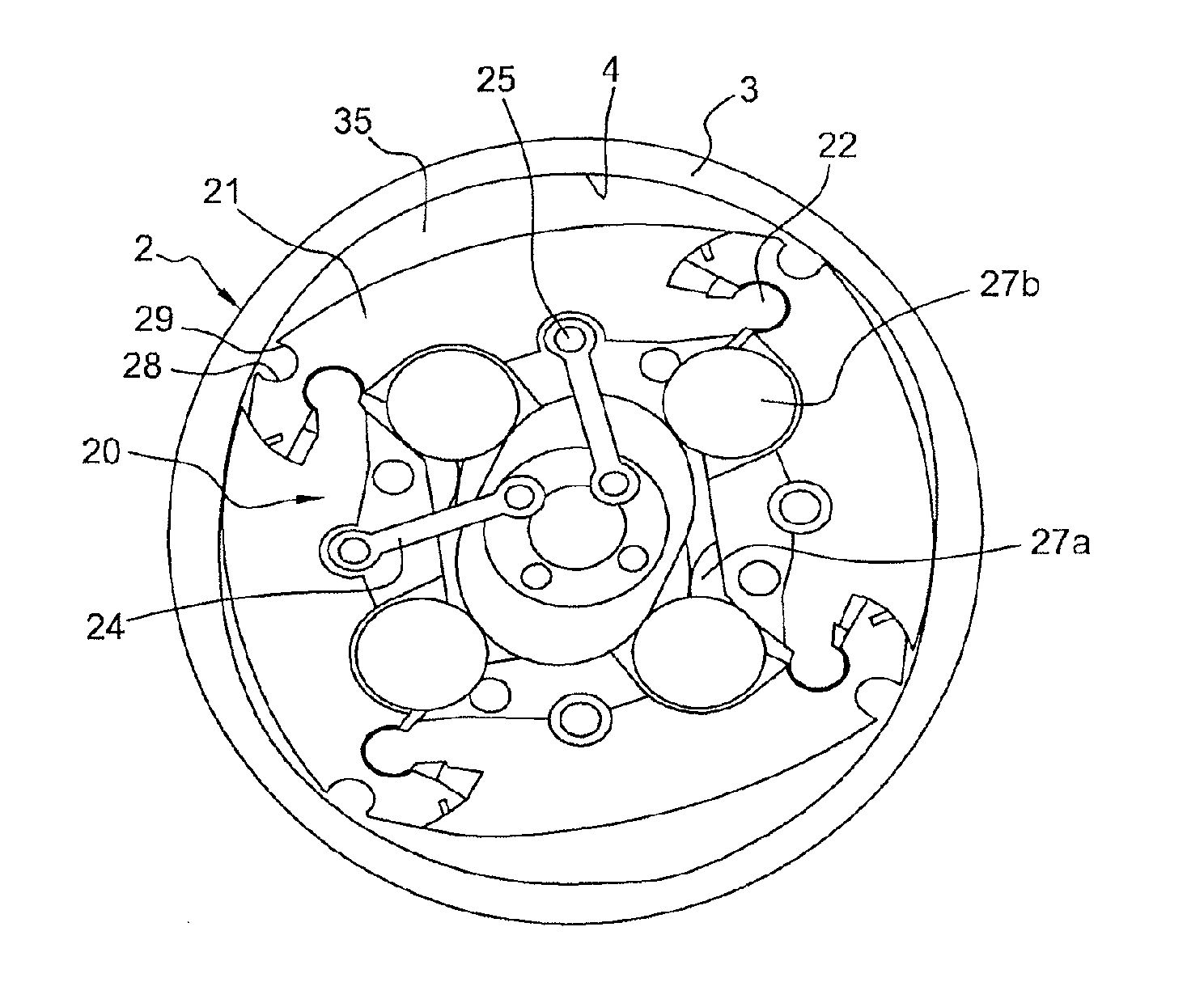
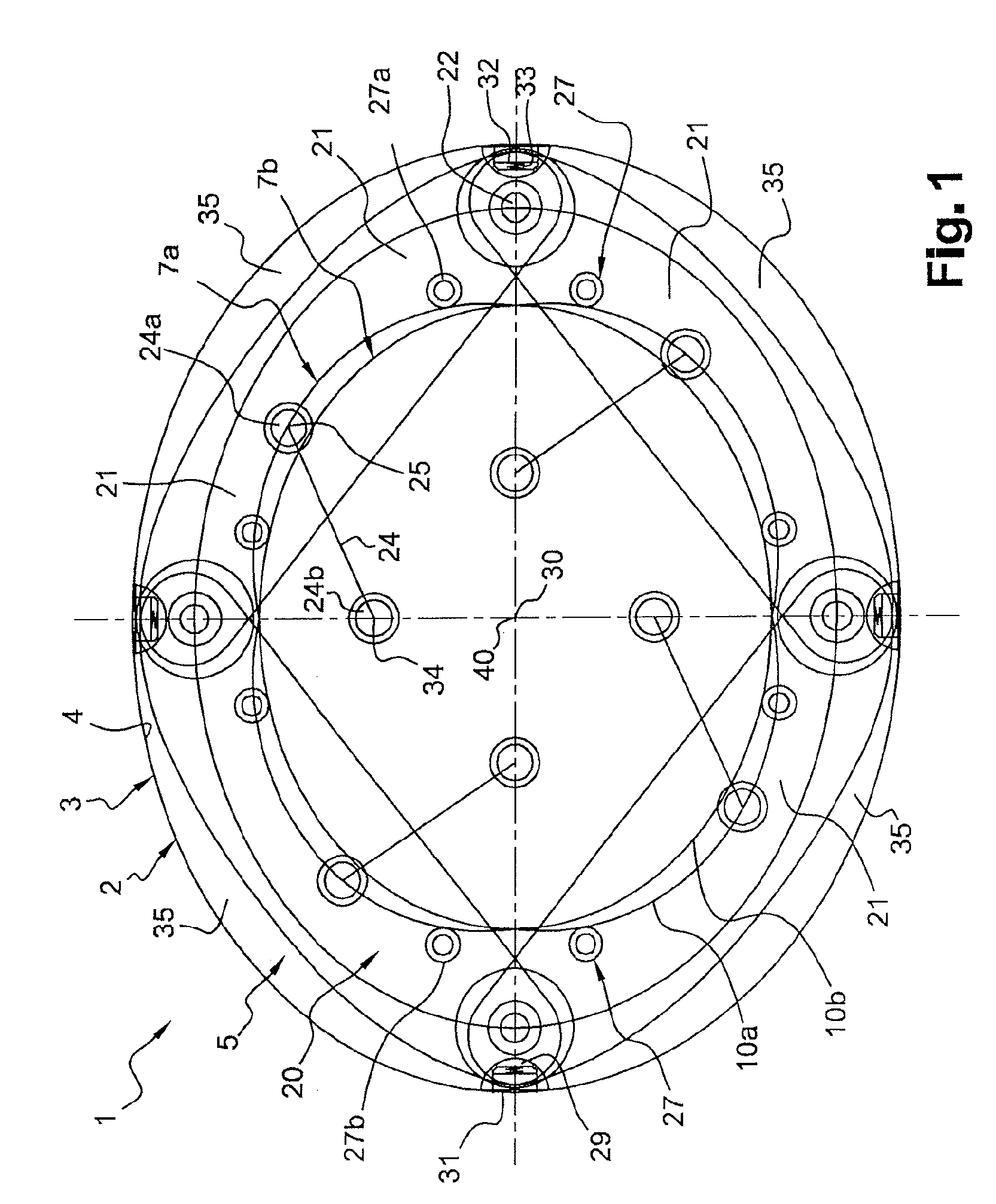
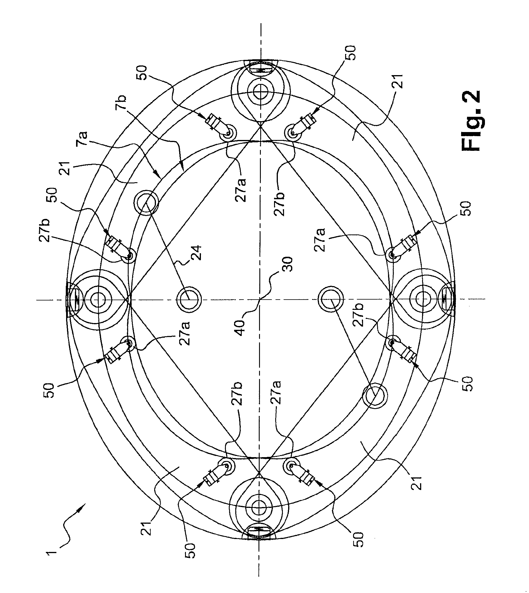
[0068]As illustrated in FIGS. 1, 2, 3 and 8, a rotary piston 21 mechanism 1 includes an outer enclosure 2 forming a stator inside which a rotary assembly 20 forming a rotor moves.

[0069]All of the reasoning described hereafter is valid for a polygon with n apices. The following reasoning is based on an embodiment with a polygon having four apices, or with four pistons forming an articulated deformable diamond, this example not being limiting.

[0070]The outer enclosure 2 in the embodiment illustrated in FIGS. 1, 2, 3 and 8 includes a single-piece body 3 generally made from steel, forming a volume with two identical ellipsoidal bases, in which an ellipsoid-shaped through cavity 5 is bored. The inner surface 4 of said cavity 5 is advantageously glazed so as to give it a surface state satisfactory for the applications of the mechanism 1.

[0071]The outer enclosure 2 also includes two lateral ellipsoid-shaped flanges 6a, 6b, shown in FIGS. 6 and 7, closing the through cavity 5 at each of the...


PUM


Abstract

The present invention relates to a mechanism (1) having rotary pistons (21), said mechanism comprising an outer enclosure (2) forming a stator in which a rotary assembly (20) forming a rotor moves, the rotary assembly (20) including: a plurality of pistons (21) forming a hinged polygon, each piston (21) defining a positive-displacement chamber (35) with the enclosure (2), and first guide (27, 27a, 27b) that are arranged so as to engage with second guide means (7a, 7b) comprising rolling surfaces (10a, 10b) so as to drive the polygon to carry out a predetermined movement, the mechanism (1) being characterized in that it comprises a drawback device (50) that maintains contact between the guide means (27, 27a, 27b) and the rolling surfaces (10a, 10b). The invention also relates to an engine and a pump including such a mechanism (1).

Description

TECHNICAL FIELD[0001]The present invention relates to a rotary piston mechanism as well as an engine and pump using such a mechanism.BRIEF SUMMARY OF RELATED ART[0002]Rotary piston mechanisms, and in particular in their motor application, have been described in many documents, which define the geometric principles of the movement of a polygon articulated at the apices of the sides making it up; each of the sides all having the same length and each of the apices being in geometric contact with a stator shape.[0003]In particular, documents WO 01 / 88341 A1, EP 1 295 012 B1 and US 2004 / 0089251 A1 propose different solutions for resolving the problems of sealing at the apices of the polygon, and transmission of the non-constant continuous movement of the pistons formed by the straight segments defined by the adjacent apices of the polygon.[0004]All of these proposals more or less appropriately resolved all or some of the theoretical operating principles of this type of mechanism.[0005]How...

Claims


Application Information

Patent Timeline
Patent Type & Authority Applications(United States)
IPC IPC(8): F04B27/08
CPCF01C1/067F01C1/07F04C2270/12F01C21/08F01C21/106F01C1/44
Inventor KUZDZAL, PHILIPPE
Owner PK ENR
Why Eureka
Try Eureka