Electrode rotation electric conduction structure

A conductive structure and electrode technology, applied in the direction of electrode accessories, auxiliary devices, auxiliary welding equipment, etc., can solve the problems of bulky equipment, difficult installation and maintenance, failure of movable guide structure, etc., and achieve the effect of ensuring the conductive effect

Inactive Publication Date: 2015-05-20
FOSHAN BAOHANG MACHINERY EQUIP IND INTPROP SERVICES
View PDF0 Cites 1 Cited by
  • Summary
  • Abstract
  • Description
  • Claims
  • Application Information

AI Technical Summary

Problems solved by technology

Due to the high requirements for matching accuracy and spring force, the commonly used conductive structures are complex, difficult to install and maintain, high processing requirements and high manufacturing costs, and are not suitable for making small tiles.
In the existing commonly used conductive structures, if the spring force is too large, the friction between the electrode holder and the electrode shaft will be too large, causing the electrode holder to hold the electrode shaft so that the electrode shaft cannot rotate freely, and the movable guiding structure will fail; The process will inevitably lead to the wear of the electrode tile, that is, the silver sheet. After the electrode tile is worn and thinned, there will be a displacement between the electrode shaft and the electrode tile. The spring pressure cannot be adjusted, so the spring force will continue to weaken, resulting in insufficient pressure, resulting in poor electrical conductivity. And bulky equipment is bulky

Method used


Image

  • Electrode rotation electric conduction structure
  • Electrode rotation electric conduction structure

Examples


Embodiment Construction

[0013] Embodiments of the present invention are described in detail below.

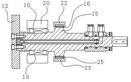
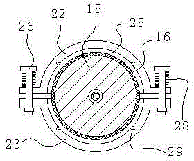
[0014] Such as figure 1 , figure 2 As shown, an electrode rotating conductive structure of the present invention includes an electrode shaft 10 with an electrode wheel 12 installed at one end, and an electrode seat 20 sleeved on the electrode shaft 10. The electrode shaft 10 is provided with a trapezoidal or rectangular section. The shaft shoulder 15, the electrode seat 20 is provided with a ring clamp, and a silver electrode tile 16 is arranged between the shaft shoulder 15 and the ring clamp, and the ring clamp includes a semi-annular upper clamp body 22 and a lower clamp body butted against each other. Body 23, the upper clamp body 22 and the lower clamp body 23 are all embracing pressing parts with variable radius, and a contraction gap is preset between the upper clamp body 22 and the lower clamp body 23, and the upper clamp body 22 and the lower clamp body 23 are in contact with the lower clam...


PUM


Abstract

The invention discloses an electrode rotation electric conduction structure. The electrode rotation electric conduction structure comprises an electrode shaft and an electrode holder, an electrode wheel is installed at one end of the electrode shaft, and the electrode shaft is sleeved with the electrode holder and provided with shaft shoulders of which the sections are trapezoid or rectangular. The electrode holder is provided with an annular clamp, silver electrode tiles are arranged between the shaft shoulders and the annular clamp, and the annular clamp comprises a semicircular upper clamp body and a semicircular lower clamp body connected with the upper clamp body in a butt joint mode. The upper clamp body and the lower clamp body are encircling pressing parts of which the radius is changeable. A shrinkage gap is prearranged between the upper clamp body and the lower clamp body, and pressing pieces for pressing the electrode tiles are arranged between the upper clamp body and the corresponding electrode tile as well as between the lower clamp body and the corresponding electrode tile. Because the clamping radius of the annular clamp for clamping the electrode tiles is changeable, the radius of the annular clamp is adjusted and shrunk, the abrasion loss of the silver pieces can be offset, it is ensured that the electric conduction structure keeps original pressure all the time, and therefore the electric conduction effect of the electric conduction structure can be ensured without frequently replacing the silver pieces.

Description

technical field [0001] The invention relates to a conductive structure, in particular to a conductive structure for electrode rotation. Background technique [0002] The conduction method of the movable conductive structure of the electrode shaft and the electrode seat inside the electrode of the traditional seam welding machine is to compress the electrode seat by a spring, so that the tapered surface of the electrode shaft and the electrode seat fit and conduct electricity. In order to achieve low rotational resistance and strong electrical conductivity in the above structural form, it is first necessary to ensure the matching accuracy between the electrode holder, the electrode tile and the electrode shaft, and secondly to ensure that the compression force of the spring reaches the maximum within the allowable range of rotational resistance. , the strength is just right. Due to the high requirements for matching accuracy and spring force, the commonly used conductive str...

Claims


Application Information

Patent Timeline
IPC IPC(8): B23K37/00
CPCB23K9/26
Inventor 黄婉雅
Owner FOSHAN BAOHANG MACHINERY EQUIP IND INTPROP SERVICES
Why Eureka
Try Eureka