Electrode rotation electric conduction structure

A conductive structure and electrode technology, which is applied in the field of electrode rotating conductive structures, can solve the problems of bulky equipment, failure of movable guide structures, high processing requirements, etc., and achieve the effect of ensuring the conductive effect

Inactive Publication Date: 2015-05-20
FOSHAN BAOHANG MACHINERY EQUIP IND INTPROP SERVICES
View PDF0 Cites 3 Cited by
  • Summary
  • Abstract
  • Description
  • Claims
  • Application Information

AI Technical Summary

Problems solved by technology

Due to the high requirements for matching accuracy and spring force, this conductive structure is complicated, difficult to install and maintain, high in processing requirements and high in manufacturing costs, and is not suitable for making small tiles.
In this kind of conductive structure, if the spring force is too large, the friction between the electrode holder and the electrode shaft will be too large, causing the electrode holder to hold the electrode shaft so that the electrode shaft cannot rotate freely, and the movable guiding structure will fail; The wear of the electrode tile, that is, the silver sheet, will cause a displacement between the electrode shaft and the electrode tile after the electrode tile is worn and thinned. Larger devices are bulky

Method used


Image

  • Electrode rotation electric conduction structure

Examples


Embodiment Construction

[0009] Embodiments of the present invention are described in detail below.

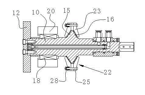
[0010] Such as figure 1 As shown, in the present invention, a seam welding machine electrode includes an electrode rotating conductive structure formed by combining the internal electrode shaft 10 and the electrode seat 20, and is connected by the support of the rolling bearing 18, so that the electrode shaft 10 is connected to the electrode seat along the shaft shoulder. The 20' ring body fits conductively.

[0011] The main structure of the electrode rotating conductive structure includes an electrode shaft 10 with an electrode wheel 12 installed at one end, and an electrode holder 20 sheathed on the electrode shaft 10. The electrode shaft 10 is provided with a trapezoidal or triangular shoulder 15 in section, so The electrode seat 29 is provided with a V-shaped annular clip body 22 adapted to surround the adjustable clip groove width surrounding the shaft shoulder 15 , and a silver sheet 16 is arr...


PUM


Abstract

The invention discloses an electrode rotation electric conduction structure. The electrode rotation electric conduction structure comprises an electrode shaft and an electrode holder, an electrode wheel is installed at one end of the electrode shaft, and the electrode shaft is sleeved with the electrode base and provided with shaft shoulders of which the sections are trapezoid or triangular. The electrode holder is provided with an annular clamp, the section of the annular clamp is in a V shape, the annular clamp surrounds the shaft shoulders in a matched mode, the width of a clamping groove of the annular clamp is adjustable, and silver pieces are arranged between the shaft shoulders and the annular clamp. Because the width of the clamping groove of the annular clamp used for clamping the silver pieces and additionally arranged on the electrode holder is adjustable, the compression amount of springs is appropriately adjusted when the silver pieces are initially installed, and the electric conduction effect is guaranteed; in the using process, abrasion to the silver pieces is generated under the action of friction force in the rotation process of the electrode shaft, at the moment, it is needed to adjust the width of the clamping groove, offset the abrasion loss of the silver pieces and guarantee that the electric conduction structure keeps original spring pressure all the time, and therefore the electric conduction effect of the electric conduction structure can be guaranteed without frequently replacing the silver pieces.

Description

technical field [0001] The invention relates to a conductive structure, in particular to a conductive structure for electrode rotation. Background technique [0002] The conduction method of the movable conductive structure of the electrode shaft and the electrode seat inside the electrode of the traditional seam welding machine is to compress the electrode seat by a spring, so that the tapered surface of the electrode shaft and the electrode seat fit and conduct electricity. In order to achieve low rotational resistance and strong electrical conductivity in the above structural form, it is first necessary to ensure the matching accuracy between the electrode holder, the electrode tile and the electrode shaft, and secondly to ensure that the compression force of the spring reaches the maximum within the allowable range of rotational resistance. , the strength is just right. Due to the high requirements for matching accuracy and spring force, this conductive structure is com...

Claims


Application Information

Patent Timeline
IPC IPC(8): B23K37/00
CPCB23K11/3036
Inventor 黄婉雅
Owner FOSHAN BAOHANG MACHINERY EQUIP IND INTPROP SERVICES
Why Eureka
Try Eureka