Electrode rotating conducting structure

A conductive structure and electrode technology, applied in the direction of flexible/rotatable wire connectors, circuits, electrical components, etc., can solve the problems of bulky equipment, complex conductive structure forms, and failure of activity-oriented structures, and achieve the effect of ensuring the conductive effect

Inactive Publication Date: 2015-05-20
FOSHAN BAOHANG MACHINERY EQUIP IND INTPROP SERVICES
View PDF0 Cites 0 Cited by
  • Summary
  • Abstract
  • Description
  • Claims
  • Application Information

AI Technical Summary

Problems solved by technology

Due to the high requirements for matching accuracy and spring force, the commonly used conductive structures are complex, difficult to install and maintain, high processing requirements and high manufacturing costs, and are not suitable for making small tiles.
In the existing commonly used conductive structures, if the spring force is too large, the friction between the electrode holder and the electrode shaft will be too large, causing the electrode holder to hold the electrode shaft so that the electrode shaft cannot rotate freely, and the movable guiding structure will fail; The process will inevitably lead to the wear of the electrode tile, that is, the silver sheet. After the electrode tile is worn and thinned, there will be a displacement between the electrode shaft and the electrode tile. The spring pressure cannot be adjusted, so the spring force will continue to weaken, resulting in insufficient pressure, resulting in poor electrical conductivity. And bulky equipment is bulky

Method used


Image

  • Electrode rotating conducting structure
  • Electrode rotating conducting structure

Examples


Embodiment Construction

[0012] Embodiments of the present invention are described in detail below.

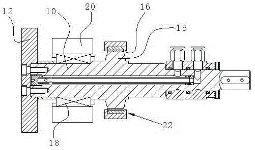
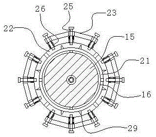
[0013] Such as figure 1 , figure 2 As shown, an electrode rotating conductive structure of the present invention includes an electrode shaft 10 with an electrode wheel 12 installed at one end, and an electrode seat 20 sleeved on the electrode shaft 10. The electrode shaft 10 is provided with a trapezoidal or rectangular section. The shaft shoulder 15, the electrode seat 20 is provided with a ring clamp, and a silver electrode tile 16 is provided between the shaft shoulder 15 and the ring clamp, and the ring clamp includes at least two arc-shaped elastic pressing pieces 22, and the elastic pressing Shrinkage gaps are preset between the sheets 22 , and gaskets 21 for pressing the electrode tiles are provided between the elastic pressing sheets 22 and the electrode tiles 16 . Since the clamping radius of the ring clamp attached to the electrode holder 20 for clamping the silver sheet (that is, the ele...


PUM


Abstract

The invention discloses an electrode rotating conducting structure, which comprises an electrode shaft and an electrode seat, wherein one end of the electrode shaft is provided with an electrode wheel, the electrode seat is arranged on the electrode shaft in a sleeving way, the electrode shaft is provided with a shaft shoulder with the trapezoidal or rectangular cross section, the electrode seat is provided with an annular clamp, a silver electrode tile is arranged between the shaft shoulder and the annular clamp, the annular clamp seat comprises at least two arc-shaped elastic press sheets, a contraction gap is preset between the elastic press sheets, and a gasket used for pressing the electrode tile is respectively arranged between the elastic press sheets and the electrode tile. The clamping radius of the annular clamp used for clamping the electrode tile is variable, so the abrasion quantity of a silver sheet can be counteracted through regulating and reducing the radius of the annular clamp, and the conducting structure is enabled to maintain the original pressure all the time, so that the conducting effect of the conducting structure can be ensured without frequently replacing the silver sheet.

Description

technical field [0001] The invention relates to a conductive structure, in particular to a conductive structure for electrode rotation. Background technique [0002] The conduction method of the movable conductive structure of the electrode shaft and the electrode seat inside the electrode of the traditional seam welding machine is to compress the electrode seat by a spring, so that the tapered surface of the electrode shaft and the electrode seat fit and conduct electricity. In order to achieve low rotational resistance and strong electrical conductivity in the above structural form, it is first necessary to ensure the matching accuracy between the electrode holder, the electrode tile and the electrode shaft, and secondly to ensure that the compression force of the spring reaches the maximum within the allowable range of rotational resistance. , the strength is just right. Due to the high requirements for matching accuracy and spring force, the commonly used conductive str...

Claims


Application Information

Patent Timeline
Patent Type & Authority Applications(China)
IPC IPC(8): H01R35/00H01R4/48B23K37/00
Inventor 黄婉雅
Owner FOSHAN BAOHANG MACHINERY EQUIP IND INTPROP SERVICES
Why Eureka
Try Eureka