Magnetic field sensor having anisotropic magnetoresisitive elements, with improved arrangement of magnetization elements thereof

a technology of anisotropic magnetoresisitive elements and magnetic field sensors, which is applied in the field of magnetic field sensors, can solve the problems of increasing the manufacturing cost of the amr sensor, the presence of said straps, and complicating the process of manufacturing the amr sensor

Active Publication Date: 2012-06-28
STMICROELECTRONICS SRL
View PDF10 Cites 21 Cited by
  • Summary
  • Abstract
  • Description
  • Claims
  • Application Information

AI Technical Summary

Problems solved by technology

The presence of said straps complicates the process of fabrication of the AMR sensor, and the manufacturing cost thereof increases in so far as it uses masks dedicated to formation of two different straps on different metal levels and to formation of metal connections (via holes) through the wafer for providing the electrical supply for biasing said straps.

Method used


Image

  • Magnetic field sensor having anisotropic magnetoresisitive elements, with improved arrangement of magnetization elements thereof
  • Magnetic field sensor having anisotropic magnetoresisitive elements, with improved arrangement of magnetization elements thereof
  • Magnetic field sensor having anisotropic magnetoresisitive elements, with improved arrangement of magnetization elements thereof

Examples


Embodiment Construction

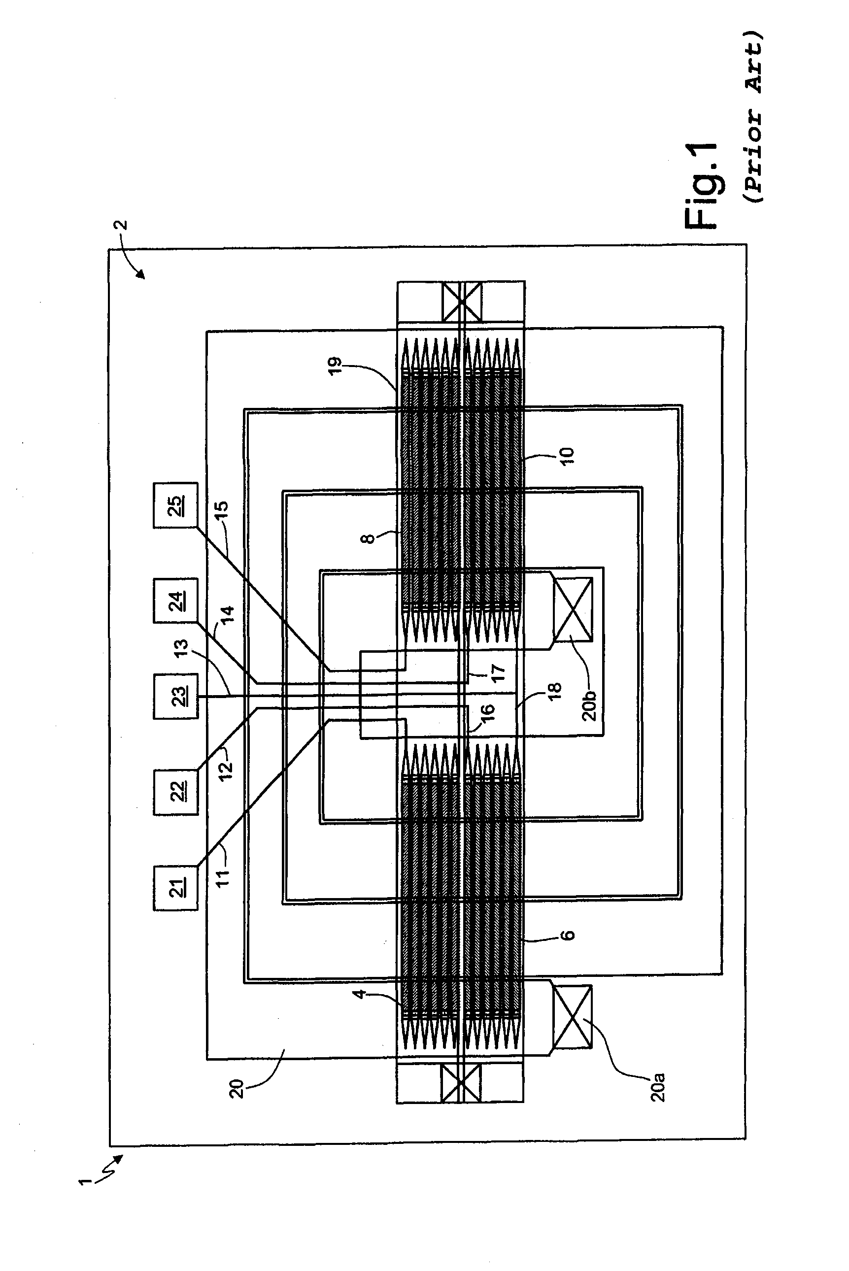
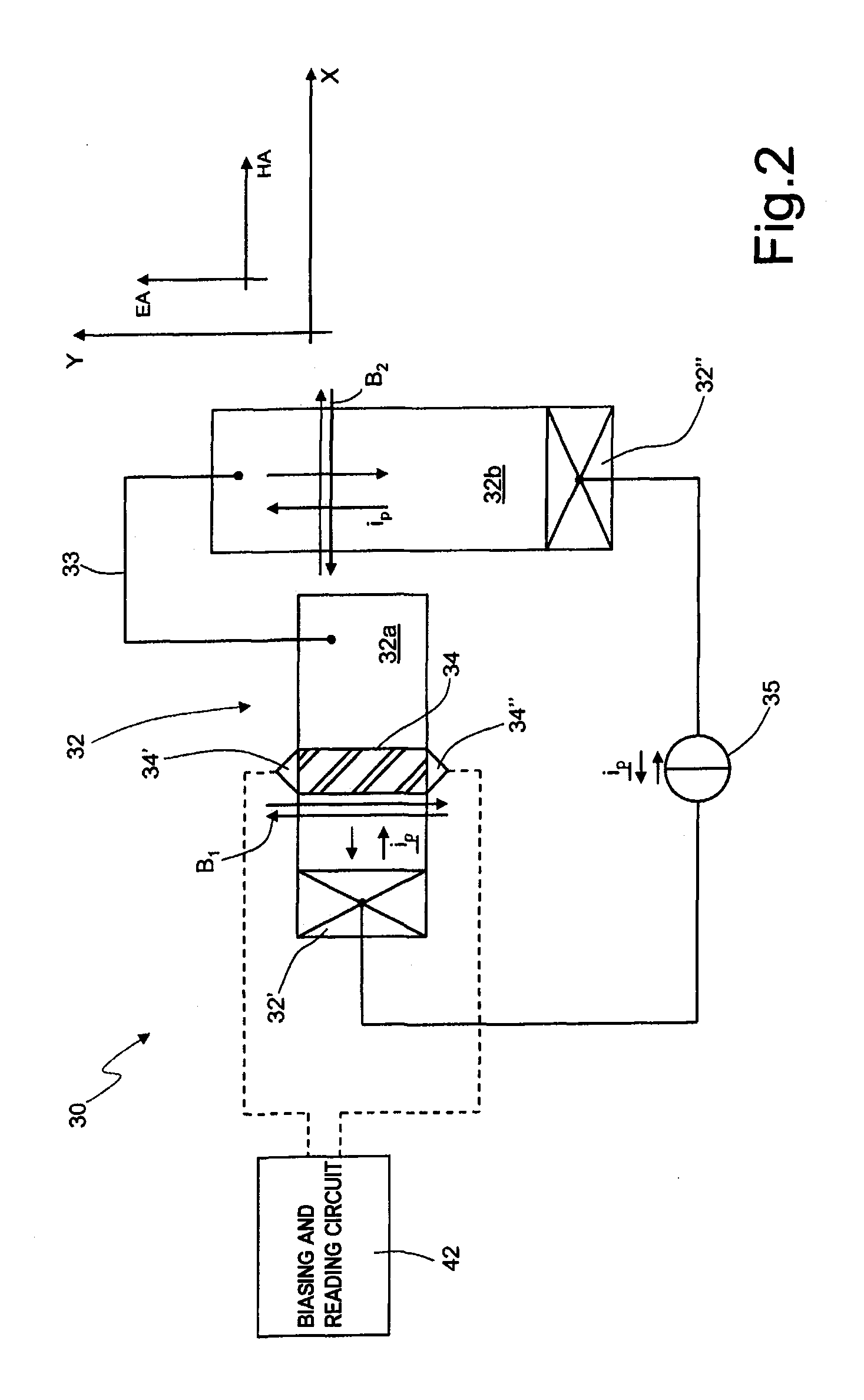
[0040]FIG. 2 shows, in top plan view and in schematic form, a magnetic-field sensor 30 according to one embodiment of the present disclosure. The magnetic-field sensor 30, unlike the magnetic-field sensor 1 of FIG. 1, comprises a magnetic-field generator 32, here in particular formed by electrically connected planar conductive strips, configured for carrying out both the set / reset operation and the operation of calibration / offset compensation of the magnetoresistive elements (just one magnetoresistive element 34 is shown in the figure) of the magnetic-field sensor 30. The magnetic-field generator 32 can hence be operated indifferently with the purpose of set / reset (as described with reference to the strap 20 of FIG. 1) or with the purpose of calibration during the testing stage or offset compensation (as described with reference to the strap 19 of FIG. 1), or simultaneously with both purposes of set / reset and calibration / offset compensation.

[0041]The magnetic-field generator 32 comp...


PUM


Abstract

An integrated magnetic-field sensor designed to detect an external magnetic field, comprising a first magnetoresistive structure for detecting the external magnetic field, the first magnetoresistive structure including first magnetoresistive means having a main axis of magnetization and a secondary axis of magnetization set orthogonal to one another. The magnetic-field sensor further comprises a magnetic-field generator, including a first portion configured for generating a first magnetic field having field lines in a first field direction, and a second portion, which is coplanar and is connected to the first portion, configured for generating a second magnetic field having field lines in a second field direction, the first magnetoresistive means being configured so that the main axis of magnetization extends parallel to the first field direction, and the secondary axis of magnetization extends parallel to the second field direction.

Description

BACKGROUND[0001]1. Technical Field[0002]The present disclosure relates to a magnetic-field sensor, in particular one comprising anisotropic magnetoresistive elements.[0003]2. Description of the Related Art[0004]Magnetic-field sensors, in particular anisotropic-magnetoresistive (AMR) sensors, are used in a plurality of applications and systems, for example in compasses, in systems for detecting ferromagnetic materials, in the detection of currents, and in a wide range of other applications, thanks to their capacity for detecting natural magnetic fields (for example, the Earth's magnetic field) and magnetic fields generated by electrical components (such as electrical or electronic devices and lines traversed by electric current).[0005]In a known way, the phenomenon of anisotropic magnetoresistivity occurs within particular ferromagnetic materials, which, when subjected to an external magnetic field, undergo a variation of resistivity as a function of the characteristics of the magnet...

Claims


Application Information

Patent Timeline
Patent Type & Authority Applications(United States)
IPC IPC(8): G01R33/12
CPCB82Y25/00G01R33/093G01R33/0011
Inventor PACI, DARIOZERBINI, SARAH
Owner STMICROELECTRONICS SRL
Why Eureka
Try Eureka