Timepiece having a mechanical movement associated with an electronic regulator

a technology of electronic regulator and mechanical movement, applied in the field of timepieces, can solve the problem of no construction proposal for such a balance generator, and achieve the effect of convenient mounting

Active Publication Date: 2005-04-07
THE SWATCH GRP RES & DEVELONMENT LTD
View PDF13 Cites 17 Cited by
  • Summary
  • Abstract
  • Description
  • Claims
  • Application Information

AI Technical Summary

Benefits of technology

[0014] Consequently, it is an object of the invention to provide a timepiece of the type indicated in the preamble by arranging the electric generator formed by the balance and the induction coil in a way that enables a mechanical watch movement to be used with the fewest possible alterations, while ensuring efficient electromagnetic coupling between the fixed part and the mobile part of the electric generator. It is an additional object to arrange the electric generator with a balance so as to be able to combine it with an automatically wound movement by altering said movement as little as possible. It is another additional object to arrange the electronic regulator in a compact form allowing, if possible, it to be housed in a case of the same size as a case intended to receive only the mechanical movement.
[0018] In a preferred embodiment, the electronic regulator includes a printed circuit board carrying at least the rectifier, a quartz resonator and the enslaving circuit, and preferably also the coil. Thus, the electronic regulator is an autonomous structural module entirely separate from the mechanical movement, which, in its entirety, except for the coil, can be located outside the mechanical movement. For example, this module can be fixed to a casing ring which surrounds the mechanical movement. This allows the electronic module to be easily mounted in a watchcase after the mechanical movement has been fitted.

Problems solved by technology

However, no construction is proposed for such a balance generator in this Patent, nor, to our knowledge, has one been made since.
One particular problem, which arises in such a watch balance generator, lies in the configuration of the magnetic circuit ensuring the coupling between the fixed coil and the balance magnets, given the neighbouring metallic weights of the mechanical clockwork-movement.
A similar problem arises in electric watches of the type in which the oscillating movement of a sprung balance assembly is maintained not by a motor spring, but by electric pulses applied to at least one fixed coil arranged opposite the trajectory of the magnets, for example as is described in U.S. Pat. No. 3,487,629 and U.S. Pat. No. 3,653,199.
The use of such a two-wheel balance in a watch of the type concerned by the present invention would be very disadvantageous, mainly because such a balance would be too cumbersome and would have too high a moment of inertia.

Method used


Image

  • Timepiece having a mechanical movement associated with an electronic regulator
  • Timepiece having a mechanical movement associated with an electronic regulator
  • Timepiece having a mechanical movement associated with an electronic regulator

Examples


Embodiment Construction

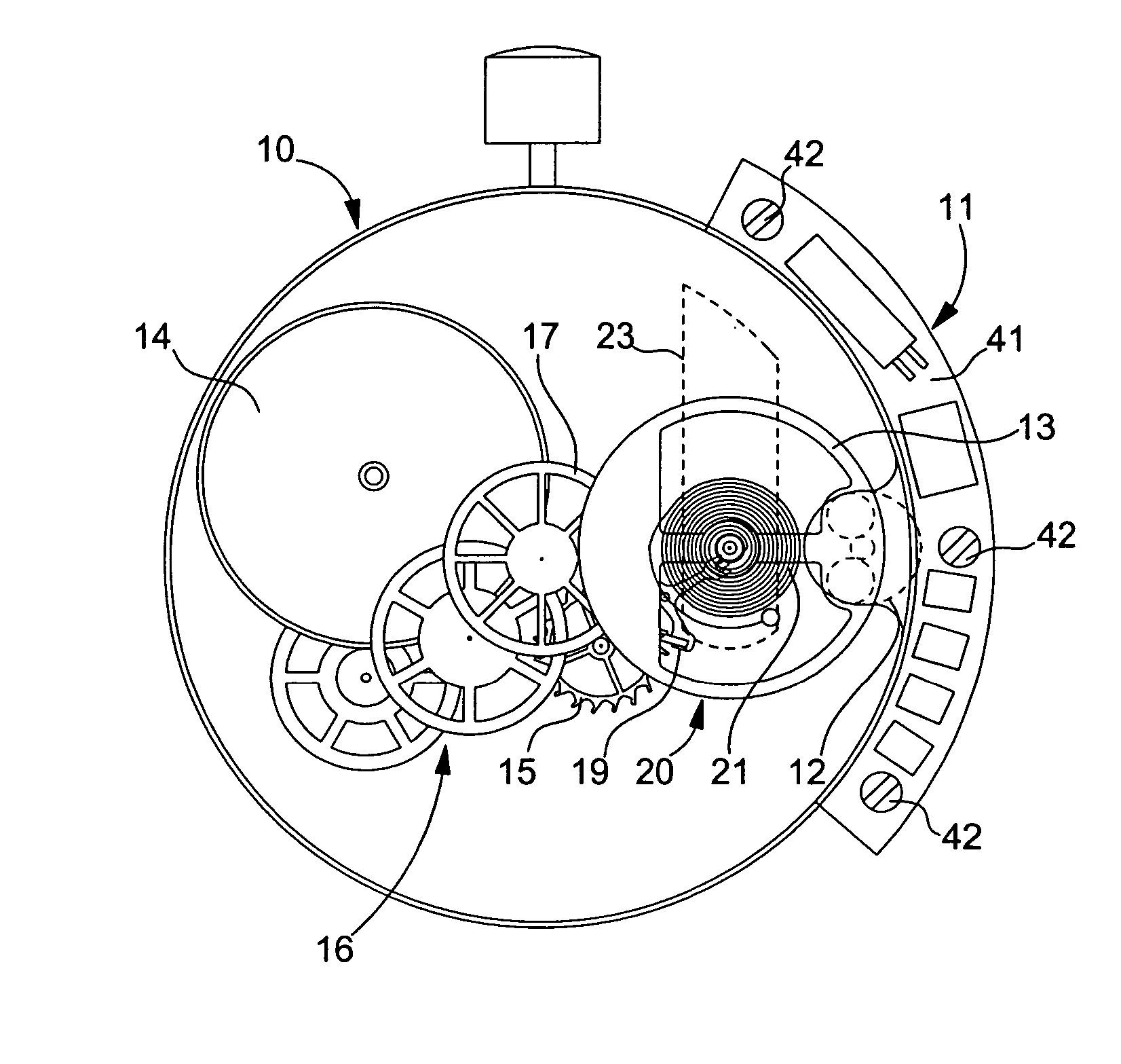
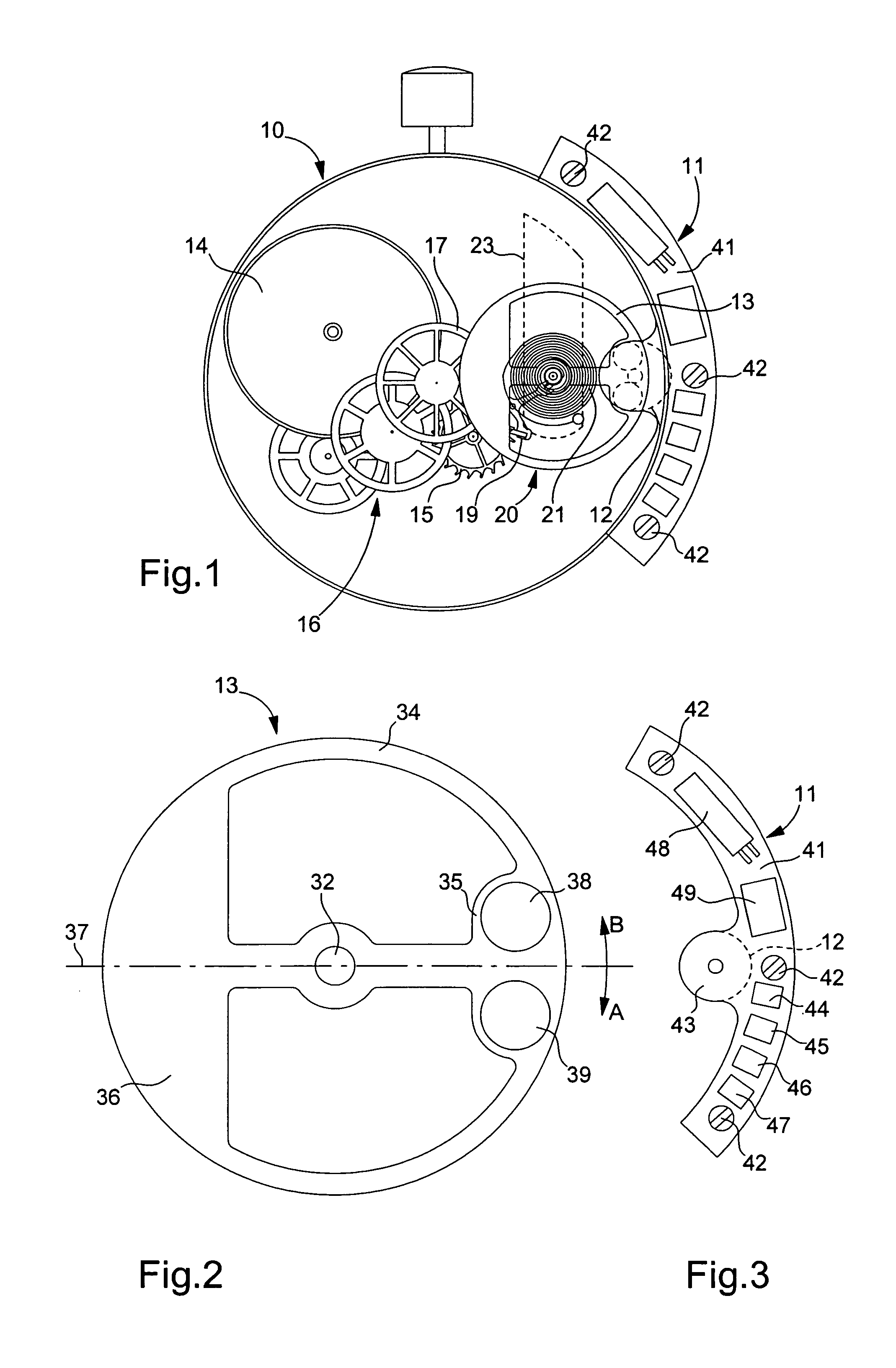
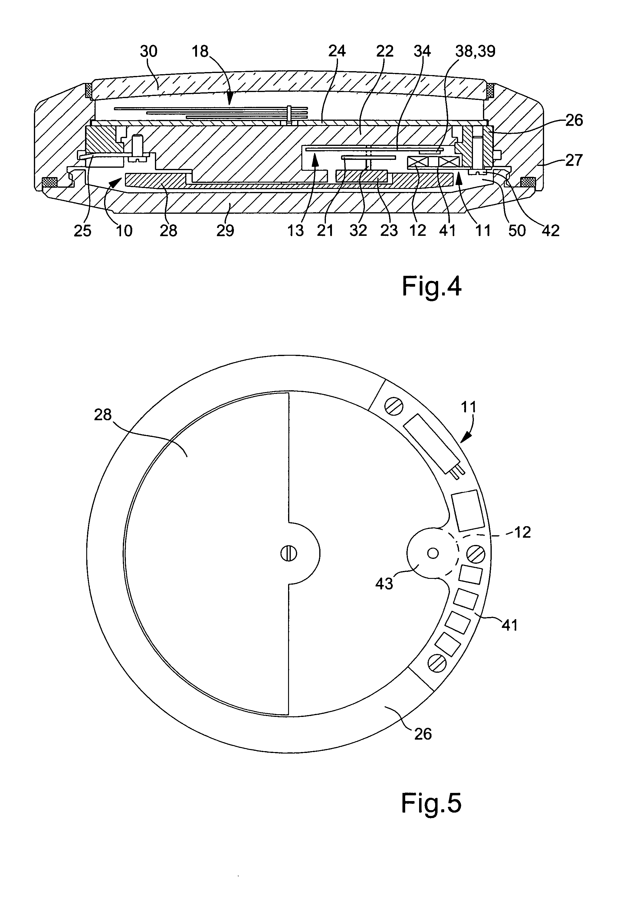
[0030] Reference will be made first of all to FIGS. 1 to 5, which show schematically the main elements of a wristwatch according to the invention, in a first embodiment. The watch includes a self-winding mechanical watch movement 10, of a common type such as the Eta 2824 calibre, and an electronic regulator made in the form of an electronic module 11 including a coil 12 which cooperates via electromagnetic coupling with balance 13 of mechanical movement 10, this balance being the only part altered with respect to the original movement.

[0031] Since movement 10 is well known, only a few of its components have been shown in the drawings, particularly a spring barrel 14 which drives an escapement wheel 15 via a gear train 16 including a central second wheel 17, which drives hands 18 of the watch. The escapement includes a pallet 19 giving pulses to the mechanical regulator 20, which includes balance 13 and a balance spring 21, the regulator being rotatably mounted between plate 22 of m...


PUM


Abstract

There is disclosed a timepiece having a mechanical clockwork-movement (10) driven by a barrel spring (14) and provided with a mechanical regulator, with a balance and a balance spring, which is associated, via electromagnetic coupling, with an electronic regulator driven by a quartz resonator. The rim of the balance (13) balance is provided with at least one pair of permanent magnets (38, 39). The electronic regulator includes a fixed coil (12) arranged for cooperating with said magnets via electromagnetic coupling, a rectifier (58) provided with at least one capacitor, and a circuit for enslaving the frequency of the mechanical regulator to the oscillator frequency by braking obtained by briefly short-circuiting the coil. In order to use a mechanical movement of a common type, in which only the balance is altered, the coil (12) is located on the side of the balance-cock (23) with respect to the balance rim. The pair of magnets (38, 39) is covered by a plate of magnetic material in order to close field lines on the side of the plate. Apart from the coil, all of the rest of the electronic module (11) is located outside the mechanical movement.

Description

[0001] This application claims priority from European Patent Application No 03022030.5 filed Oct. 1, 2003, the entire disclosure of which is incorporated herein by reference. BACKGROUND OF THE INVENTION [0002] The present invention concerns a timepiece having a mechanical clockwork-movement driven by a spring and provided with a mechanical regulator, which is associated, by electromagnetic coupling, with an electronic regulator, wherein: [0003] the mechanical regulator includes a balance spring associated with a balance rotatably mounted between a plate and a balance-cock for rotation, the balance having a rim provided with at least one pair of permanent magnets whose directions of magnetisation are substantially parallel to the axis of the balance, but in opposite directions to each other; and [0004] the electronic regulator includes at least one fixed coil arranged for cooperating with said magnets by electromagnetic coupling, a rectifier supplied by said coil and provided with at...

Claims


Application Information

Patent Timeline
Patent Type & Authority Applications(United States)
IPC IPC(8): G04B17/00G04C3/06G04C10/00
CPCG04C3/066G04C10/00
Inventor BORN, JEAN-JACQUESFARINE, PIERRE-ANDRE
Owner THE SWATCH GRP RES & DEVELONMENT LTD
Why Eureka
Try Eureka