
Monitoring downhole production flow in an oil or gas well

Inactive Publication Date: 2010-12-30
TELEDYNE INSTR INC
View PDF25 Cites 47 Cited by
  • Summary
  • Abstract
  • Description
  • Claims
  • Application Information

AI Technical Summary

Benefits of technology

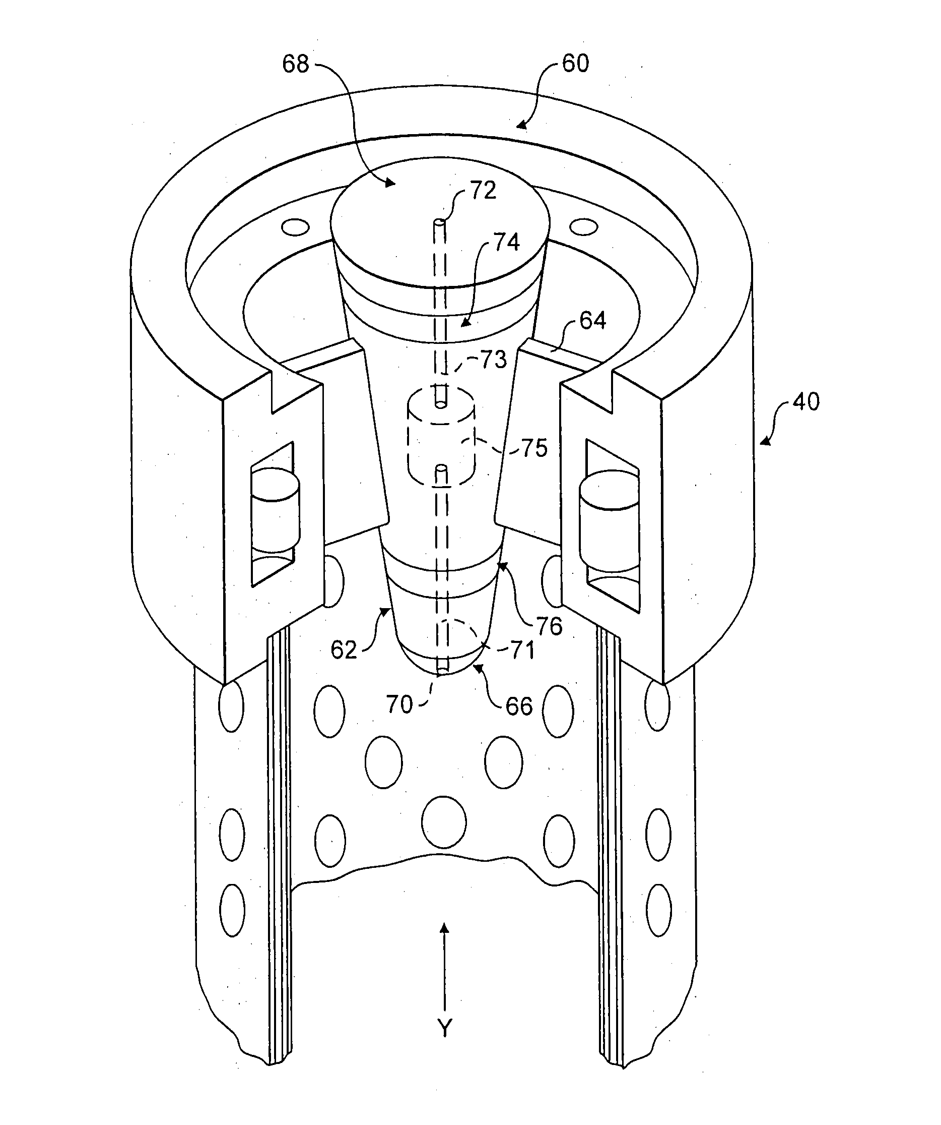
[0015]The claimed apparatus thus provides a compact arrangement for sensing erosion of the sample layer, whilst at the same time providing structural integrity to the well. Advantageously, the sample layer may be integrally formed with the sand screen or may be formed as a shroud for the sand screen, thus providing further economy of space in the confined downhole environment. Further flow sensors (e.g. for measuring temperature, pressure and acoustics) may be included in the apparatus to provide additional information concerning the production flow from the gravel pack into the sand screen. Thus anomalous well conditions may be detected early to enable well operators to take action if necessary.
[0021]In one embodiment, the deducing step comprises deducing whether the gravel pack has fluidised. Such information can provide an early warning of potential failure of the sand screen.

Problems solved by technology

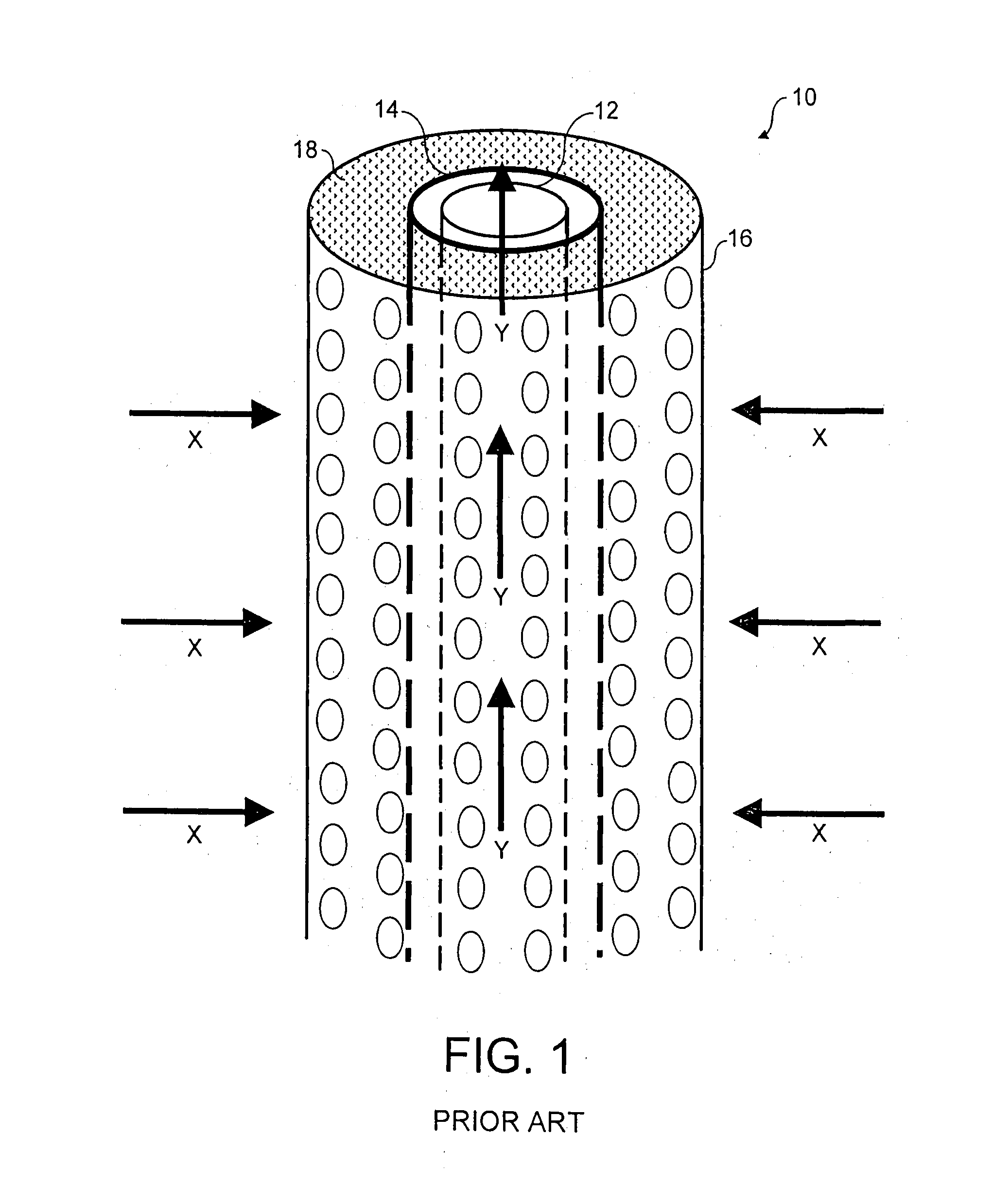
Sand or silt flowing into a wellbore from unconsolidated formations (again, see arrows X in FIG. 1) can accumulate within the wellbore, leading to reduced production rates and damage to subsurface production equipment.
Due to its highly abrasive nature, sand contained within the production streams can result in the erosion of tubing, flowlines, valves and processing equipment.
In addition to erosion, excessive sand entrained in a fluid may cause blockage of the fluid flow through the production tubing.
The problems caused by sand production can significantly increase operational and maintenance expenses and can lead to a total loss of the well 10.
If fines are produced, a potential exists to cause erosion damage to the sand screen 14 and production tubing 12.
This will therefore potentially further accelerate the localised erosion.
As erosion progresses, the sand screen 14 could eventually experience erosion damage of the mesh to the extent of reaching the size of the gravel.
This highly turbulent flow regime will potentially cause further accelerated erosion of the external surface of the sand screen 14.

Method used


Image

  • Monitoring downhole production flow in an oil or gas well
  • Monitoring downhole production flow in an oil or gas well
  • Monitoring downhole production flow in an oil or gas well

Examples


Embodiment Construction

[0033]As discussed above, the present invention relates to methods and apparatuses for monitoring a downhole production flow in an oil or gas well. The well is generally of the type described above with reference to the prior art. In particular, the well 10 has production tubing 12, a sand screen 14 disposed concentrically around the production tubing 12, an outer casing 16, and a gravel pack 18 disposed annularly between the sand screen 14 and the outer casing 16. The methods and apparatuses described relate to monitoring downhole production flow within the production tubing 12 and / or through the sand screen 14. In addition this monitoring information is used to understand the stability of the gravel pack and / or the condition of the sand screen 14.

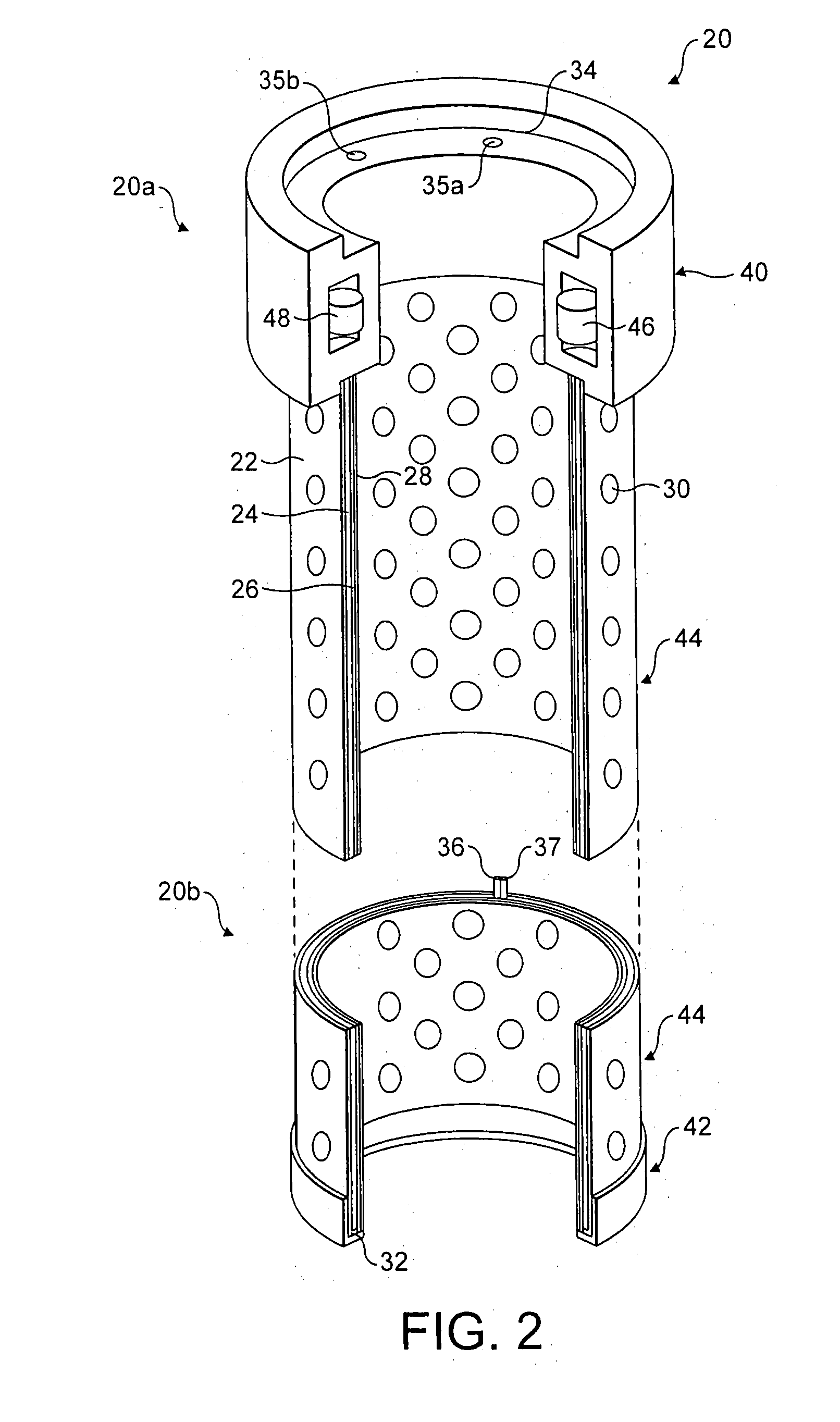
[0034]Let us first consider a substantially cylindrical apparatus 20, as shown in FIG. 2, for monitoring a production flow from the gravel pack 18 into the sand screen 14.

[0035]A typical sand screen 14 is many-layered and includes a wire ...


PUM


Abstract

An apparatus monitors a production flow from a gravel pack into a tubular sand screen disposed concentrically around downhole production tubing in an oil or gas well. A tubular sample layer is disposed concentrically around the sand screen to be exposed to the radial production flow in use. The sample layer is electrically insulated from the production tubing in use. An erosion sensor provides a signal which varies in dependence upon an electrical resistance of the sample layer, which is related to the erosion of the sample layer. An apparatus also monitors a substantially longitudinal production flow through downhole production tubing in an oil or gas well. A method and apparatus are used to monitor the condition of a gravel pack within an oil or gas well. Other methods monitor temperature or pressure conditions within an oil or gas well.

Description

FIELD OF THE INVENTION[0001]The present invention relates to methods and apparatuses for monitoring downhole production flow in an oil or gas well. The well is generally of the type having production tubing, a sand screen disposed concentrically around the production tubing, an outer casing, and a gravel pack disposed annularly between the sand screen and the outer casing. The methods and apparatuses described herein relate to monitoring downhole production flow within the production tubing and / or through the sand screen.BACKGROUND OF THE INVENTION[0002]Hydrocarbon fluids such as oil and natural gas are obtained from a subterranean geological formation, referred to as a reservoir, by drilling a well that penetrates the hydrocarbon-bearing formation. Once a wellbore has been drilled, the well must be “completed”. Completion is the process in which the well is enabled to produce hydrocarbons. A completion involves the design, selection and installation of equipment and materials in or...

Claims


Application Information

Patent Timeline
IPC IPC(8): E21B47/00E21B47/10
CPCE21B43/04E21B43/08E21B47/102E21B47/10E21B43/082E21B47/113E21B43/02E21B43/084E21B43/086E21B43/088E21B43/108E21B47/00
Inventor HEMBLADE, BARRY JOHN
Owner TELEDYNE INSTR INC
Learn More