System, method and control unit for diagnosis and life prediction of one or more electro-mechanical systems

a technology of electromechanical systems and systems, applied in the direction of program control, electric programme control, instruments, etc., can solve problems such as system shutdown and unscheduled maintenance, damage to surface integrity, geometry, or internal structure, and failure of electromechanical systems during operation

Active Publication Date: 2022-10-25
SIEMENS AG
View PDF7 Cites 0 Cited by
  • Summary
  • Abstract
  • Description
  • Claims
  • Application Information

AI Technical Summary

Benefits of technology

[0006]It is an object of the present disclosure to accurately model the electro-mechanical systems for accurate diagnosis and life prediction of the electro-mechanical systems individually and in combination.
[0035]According to an embodiment, a further failure in the electro-mechanical system is predicted based on the predicted performance. The term “further failure” refers to a failure that may take place subsequent to a first failure that was used to determine the RUL. The further failure is predicted by comparing the predicted performance of the electro-mechanical system and predicted performance of the system model. Therefore, the present disclosure is advantageous as it is able to predict potential failure of the electro-mechanical system.
[0036]According to another embodiment, a control command is generated based on the predicted further failure of the electro-mechanical system. The control command includes change in input parameters, reduction in load, information regarding back-up to a controller of the electro-mechanical system, etc. Therefore, the present disclosure enables automatic intelligent decisions to be taken promptly on a shop floor of an industrial automation environment or on the electro-mechanical system itself.
[0088]Therefore, the present disclosure is advantageous as it will eliminate experts for interpreting performance of the electro-mechanical system. Diagnosis and life prediction through this disclosure may be used by the operating personnel to optimize spare parts requirements.

Problems solved by technology

Electro-mechanical systems during operation experience failure due to fatigue or creep or fracture caused by either external impact or internal structural weakness.
The failure leads to damage of surface integrity, geometry, or internal structure.
If the failure is not detected at an early stage, the electro-mechanical systems may lead to system shutdown and unscheduled maintenance.
The physics-based model is limited as the accuracy of the model is not validated.
Accordingly, such methods are unable to diagnose the electro-mechanical performance over time and therefore, are unable to accurately predict maintenance and down-time of the electro-mechanical systems.
Further, the models are not scalable to multiple electro-mechanical systems, which make determination of reliability of the multiple electro-mechanical system difficult.

Method used


Image

  • System, method and control unit for diagnosis and life prediction of one or more electro-mechanical systems
  • System, method and control unit for diagnosis and life prediction of one or more electro-mechanical systems
  • System, method and control unit for diagnosis and life prediction of one or more electro-mechanical systems

Examples


Embodiment Construction

[0105]Various embodiments are described with reference to the drawings, wherein like reference numerals are used to refer to like elements throughout. In the following description, a large gas turbine has been considered as an example of a technical system for the purpose of explanation. Further, numerous specific details are set forth in order to provide thorough understanding of one or more embodiments. These examples must not be considered to limit the application to large gas turbine and includes any technical system that is capable of overcoming limitation of the sensors. It may be evident that such embodiments may be practiced without these specific details.

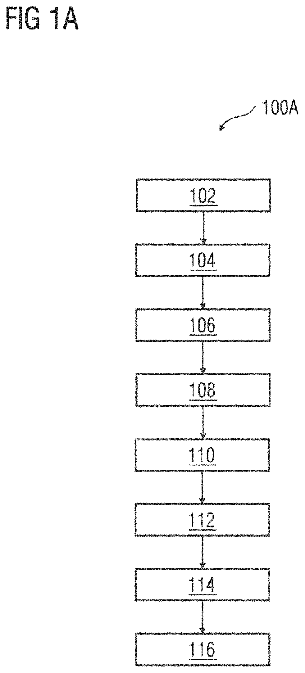
[0106]FIG. 1A is a flowchart illustrating a method 100A of diagnosis and life prediction of an electro-mechanical system. As used herein, “electro-mechanical system” refers to systems or devices that convert electrical energy into mechanical movement or vice versa. The electro-mechanical system may include one or more compo...


PUM


Abstract

Systems, methods, and control units for diagnosis and life prediction of one or more electro-mechanical system are provided. One method includes receiving sensor data from a plurality of sensors associated with operation of the electro-mechanical system. The method includes determining at least one system response associated with at least one failure mode of the electro-mechanical system from the sensor data, wherein the sensor data is indicative of the at least one failure mode of the electro-mechanical system. The method further includes receiving at least one simulated response associated with the at least one failure mode of the electro-mechanical system, wherein the at least one failure mode is simulated on a system model of the electro-mechanical system. The method includes generating a hybrid model of the electro-mechanical system in real-time based on the at least one system response and the at least one simulated response, wherein the hybrid model combines the at least one system response and the at least one simulated. The method also includes generating a diagnosis of the electro-mechanical system based on the hybrid model, wherein the diagnosis includes identification of one or more failures in the electro-mechanical system and wherein the one or more failures indicates initiation of degradation of the one or more electro-mechanical system. The method includes predicting a life trend of the electro-mechanical system based on the diagnosis.

Description

[0001]The present patent document is a § 371 nationalization of PCT Application Serial No. PCT / EP2018 / 076259, filed Sep. 27, 2018, designating the United States, which is hereby incorporated by reference, and this patent document also claims the benefit of European Patent Application No. 17194193.3, filed Sep. 29, 2017, which is also hereby incorporated by reference.TECHNICAL FIELD[0002]This disclosure relates to monitoring and controlling operation of an electro-mechanical system in real-time.BACKGROUND[0003]Electro-mechanical systems during operation experience failure due to fatigue or creep or fracture caused by either external impact or internal structural weakness. The failure leads to damage of surface integrity, geometry, or internal structure. If the failure is not detected at an early stage, the electro-mechanical systems may lead to system shutdown and unscheduled maintenance.[0004]Monitoring operation of electro-mechanical systems is used for failure detection and diagno...

Claims


Application Information

Patent Timeline
Patent Type & Authority Patents(United States)
IPC IPC(8): G05B19/418F16C41/00G05B23/02G06Q10/04G06Q10/06G06Q10/00
CPCG05B19/41885F16C41/00G05B23/0254G05B23/0283G06Q10/04G06Q10/067G06Q10/06375G06Q10/20F16C2233/00G05B2219/50185G05B17/02
Inventor HANDE, VIDYABHUSHANANAIR, P. V. SUDEV
Owner SIEMENS AG
Why Eureka
Try Eureka