Device and method for tightening a safety belt serving to protect occupants in a vehicle

a technology for safety belts and occupants, applied in vehicle safety belts, axially engaging brakes, seating furniture, etc., can solve the problems of high design cost, inability to achieve adaptive systems which guarantee the braking of safety belts, and cannot be independent of accident seats and passengers. , to achieve the effect of low failure potential

Inactive Publication Date: 2010-09-28
FRAUNHOFER GESELLSCHAFT ZUR FOERDERUNG DER ANGEWANDTEN FORSCHUNG EV
View PDF7 Cites 0 Cited by
  • Summary
  • Abstract
  • Description
  • Claims
  • Application Information

AI Technical Summary

Benefits of technology

[0006]The invention is a belt brake for a safety belt which serves to protect occupants in a vehicle and which can be wound onto or unwound from a belt drum mounted rotationally about a belt shaft, so that with the lowest possible number of individual components, which should each have a low failure potential, controlled unwinding movement of the safety belt will be possible, depending on the crash situation and the vehicle occupants to be protected. The unwinding of the safety belt, controlled by means of the belt brake according to the invention, should contribute to matching the occupant retardation to the accident phenomenon.
[0010]Due to the reduction according to the invention of the axial distance along the belt shaft between the at least one braking means and the two axially opposing thrust bearings, a situation is created in which the actuator element, when actuated, must perform a slightly axial actuator movement which gives rise to the braking force directed to the at least one braking means. The braking paths required for application of the braking force can be minimized by the thrust bearings, which are spaced only a short distance apart and the at least braking means provided between them, thereby decisively reducing the response time of the braking mechanism.
[0012]In a preferred exemplary embodiment of the belt brake according to the invention, staked actuators of piezoceramic materials may be used which, when an electrical voltage is applied, undergo a variation in length proportional to the electrical voltage. The variation in length, in the presence of an external mechanical force, generates proportional compressive forces which, according to the invention, are used to supply the braking forces. Although the forces that can be generated due to the length extension of piezo stacked actuators are very high relative to the applied electrical energy invested, such materials need only expand very short distances. It is necessary to take into consideration these properties on which the converter materials are based when they are used as actuator elements within the framework of the belt brake. Any distance along which the converter material is capable of expanding must be regarded as a loss of force potential if the converter material is able to expand without external mechanical force. It is therefore necessary to minimize any tolerances, assembly and functional clearances between the converter element and the thrust bearings in order to obtain an immediate force effect between the thrust bearings and the braking means located between them during the longitudinal expansion of the actuator element.
[0013]Since the operator friendliness of the safety belt should be uninfluenced by the belt brake according to the invention, the process of the safety belt unwinding from and winding onto the belt drum should take place in an unobstructed free run. It is therefore necessary to allow a free gap of several tenths of a millimeter between the thrust bearings actively connected to the belt shaft and the at least one braking means which cannot be closed by the longitudinal expansion of the piezo staked actuators. For this reason the belt brake according to the invention provides a type of differential design which enables the intermediate gap required for free running of the safety belt to be closed by merely actuating the safety belt, and on the other hand achieving the application of braking force exclusively by activating the actuator. Any assembly and functional clearances are overcome by a mechanical means which, as will be described in the following with reference to the exemplary embodiments, is designed in the form of a cam plate or a spindle with a sliding nut which because of a functionally determined rotation of the belt shaft, initiated by the unwinding or winding of the safety belt, is able to convert the rotational movement to a translatory movement axially to the belt shaft. Due to the translatory movement in the axial direction to the belt shaft, the distance between both thrust bearings is reduced in order to minimize any intermediate gaps between the thrust bearings and the at least one braking means, so that although on the one hand a minimum freedom of movement of the braking means relative to the thrust bearings is still guaranteed, this ensures on the other hand that the frictional surfaces provided between the braking means come into contact without force with each other and with the corresponding thrust bearings. In this position, which can be achieved merely by manual actuation of the safety belt by unwinding it from the belt drum, the longitudinal extension of the piezo actuators orientated axially towards the belt shaft is able to generate a braking force between the corresponding braking means and the thrust bearings. The frictional contact caused by the longitudinal expansion between the braking means and the thrust bearings results in a braking moment acting on the belt shaft, the size of which may ultimately be selected by the choice of electrical voltage applied to the piezo actuators. The belt brake according to the invention therefore provides the possibility of a freely selectable modulation of the braking forces, and, in particular, the braking force can be repeatedly reduced and regenerated according to the accident situation.
[0014]Data from pre-crash sensors is preferably used for actuating the piezo actuators in order to generate suitable braking forces even before the crash energy becomes active. It is also possible to perform the unwinding movement of the safety belt in a controlled manner, particularly in the event of a crash. For example, controlled unwinding of the safety belt may contribute to matching the occupant retardation to the accident process. The vehicle occupants could be given free space, instead of the conventional mechanical control, particularly at lower crash speeds, so that the retardations are reduced, which has a positive influence on the severity of injuries. Even at high crash speeds a controlled belt force-time curve may contribute to reducing acceleration peaks and therefore of optimizing occupant protection.

Problems solved by technology

Adaptive systems which guarantee braking of the safety belt, independently of the accident seat and passengers, cannot be achieved or can only be achieved at a high design cost.
However, the belt tightening system described in the above-mentioned patent specification has a multiplicity of individual components whose susceptibility influences the reliability of the entire system.

Method used


Image

  • Device and method for tightening a safety belt serving to protect occupants in a vehicle
  • Device and method for tightening a safety belt serving to protect occupants in a vehicle
  • Device and method for tightening a safety belt serving to protect occupants in a vehicle

Examples


Embodiment Construction

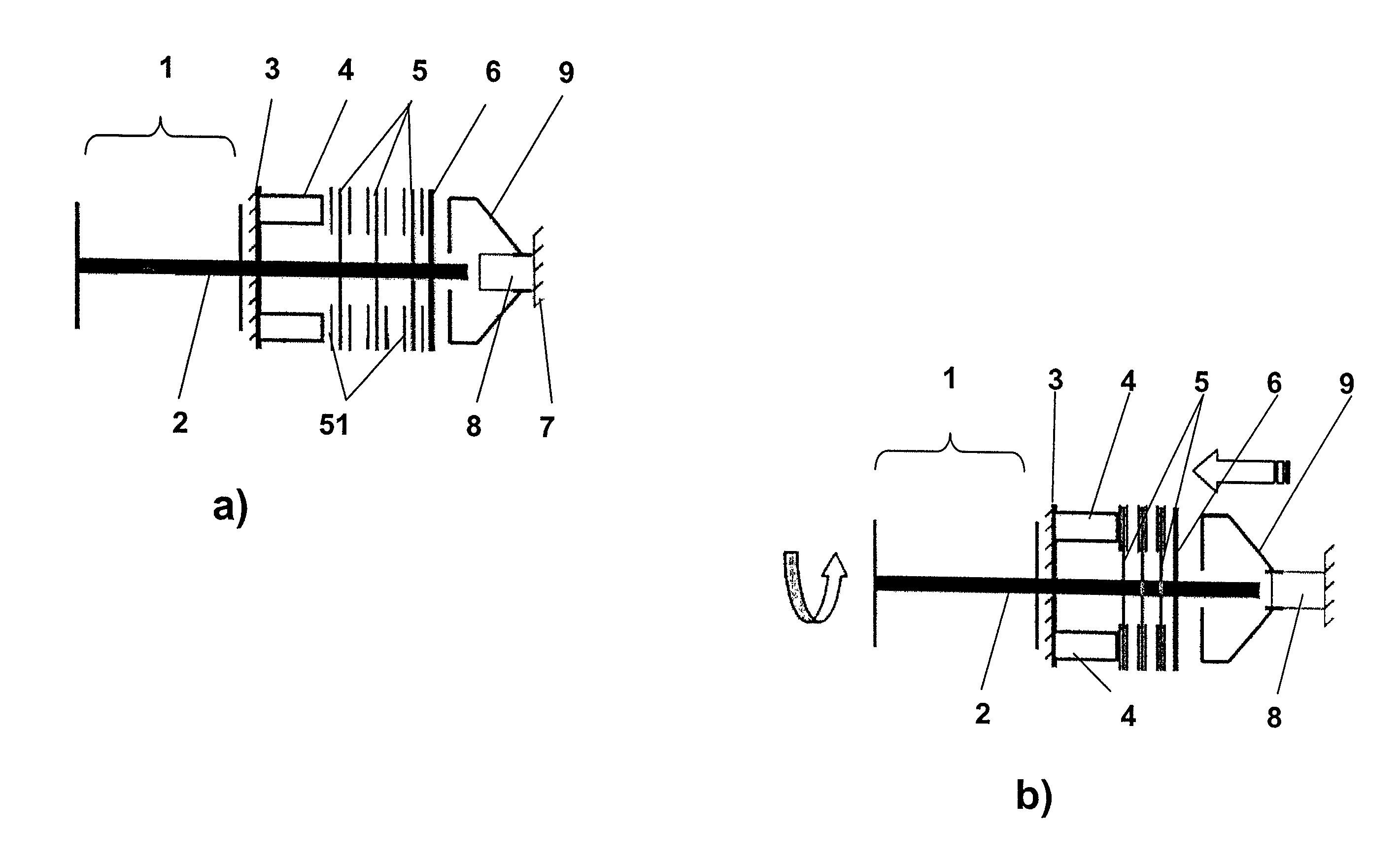
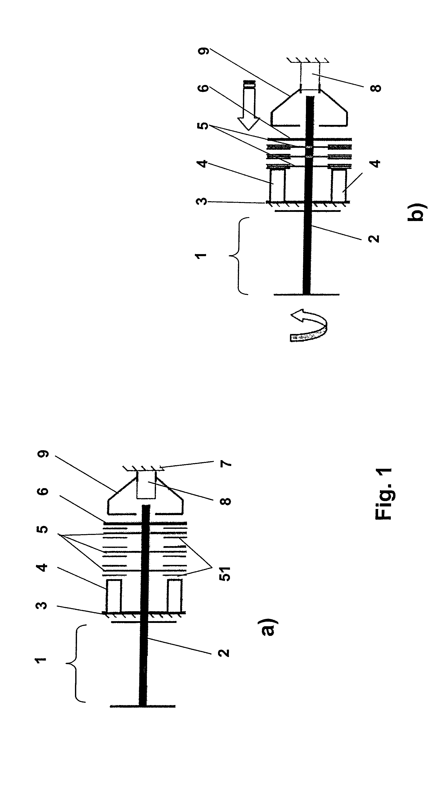
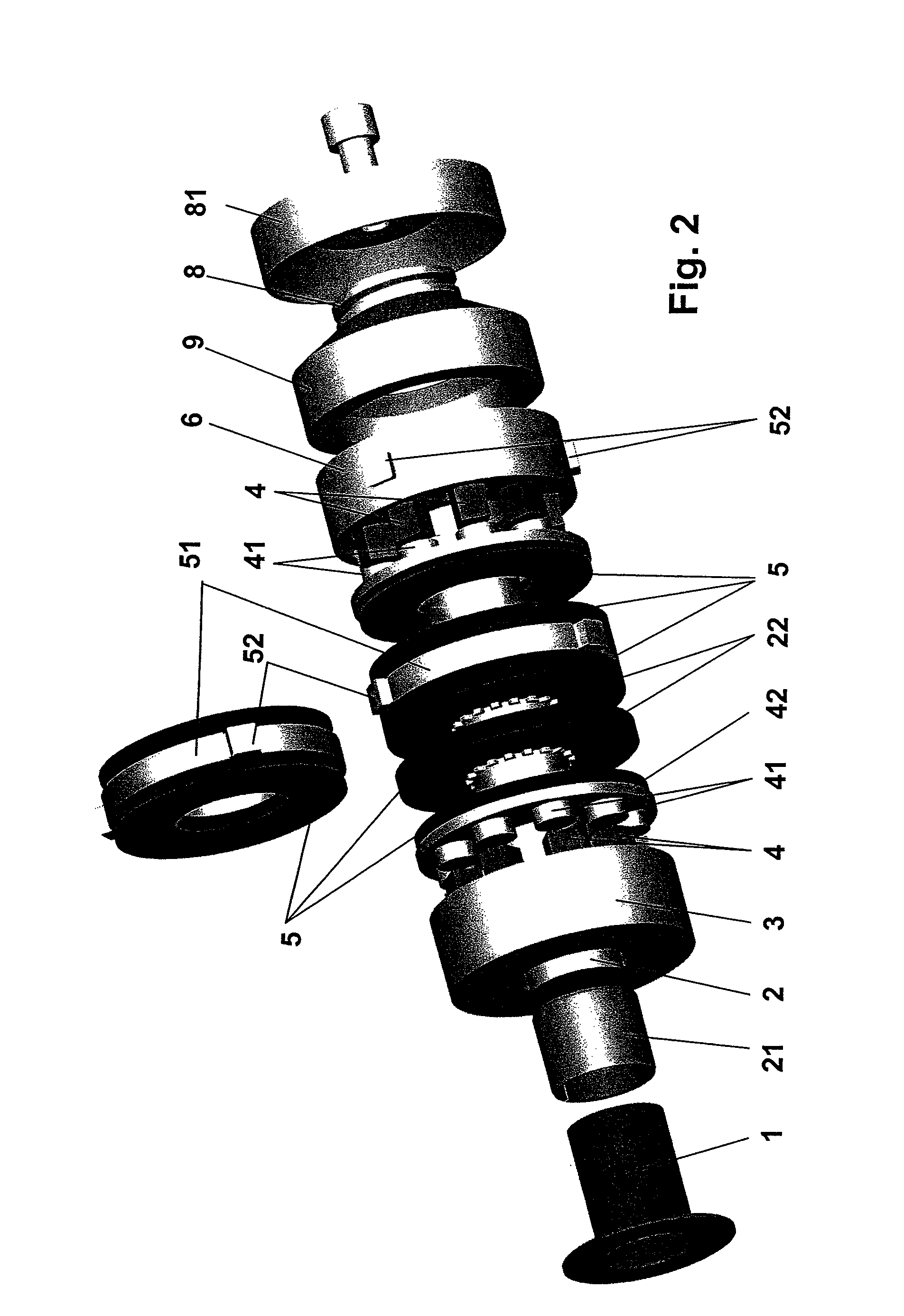
[0024]FIGS. 1a and b show a schematized belt brake which, in the case of FIG. 1a, is in the first position, that is in the state of rest, in which the safety belt (not shown) is wound more or less completely onto belt drum 1. Belt drum 1 has a belt shaft 2, which projects unilaterally from belt drum 1, along which are arranged subsequent components comprising the belt brake 5. A thrust bearing 3, which is not necessarily arranged in a rotationally fixed manner, but with a fixed axial position relative to belt shaft 2, is provided immediately adjacent to belt drum 1. Thrust bearing 3 is preferably designed in the shape of a disc and has at least two and preferably a multiplicity of actuator elements 4 distributed uniformly along the disc on the disc side facing away from belt drum 1. The actuator elements are each advantageously piezo stacking actuators discs of the brake, which are connected in a rotationally fixed and axially displaceable manner to belt shaft 2, are connected along...


PUM


Abstract

A belt brake is described for a safety belt for protecting occupants in a vehicle, which belt can be wound onto and unwound from a belt drum mounted rotationally about a belt shaft. A method for locking a safety belt is also described. The invention comprises at least one displaceable braking element for displacement along the belt shaft which is rotationally fixed to the belt shaft and is located between a first and a second thrust bearing. A first thrust bearing is forcibly guided along the belt shaft, thereby enabling the first thrust bearing to be transferred from a first position, in which the safety belt is wound on the belt drum with an axial distance a1 between the at least one braking element and the first thrust bearing, and to a second position, in which the safety belt is at least partially unwound from the belt drum with an axial distance a2 between the at least one braking element and the at least one thrust bearing where a2<11. At least one actuator element is actuated in the second position to generate a braking force which acts along the belt shaft between the first and second thrust bearings and which is orientated towards the at least one braking element.

Description

BACKGROUND OF THE INVENTION[0001]1. Field of the Invention[0002]The invention relates to a belt brake for a safety belt serving to protect occupants in a vehicle, which belt can be wound onto and unwound from a belt drum mounted rotationally about a belt shaft. Furthermore, a method is described for locking a safety belt serving to protect occupants in a vehicle.[0003]2. Description of the Prior Art[0004]Modern safety belt systems generally comprise a plurality of mechanically passively working systems which are intended to guarantee that the vehicle occupants are subjected to the lowest possible loads during an accident, and also have, if possible, no contact with the vehicle interior, not even with the parts which may penetrate the passenger compartment due to the impact. Almost all devices of prior art for braking or locking safety belts provide passively acting closing devices which, can be activated suddenly, independently of the accident situation and the vehicle occupants to ...

Claims


Application Information

Patent Timeline
Patent Type & Authority Patents(United States)
IPC IPC(8): B60R22/34
CPCB60R22/3413B60R2022/285B60R2022/288B60R22/34B60R22/36B60R22/343
Inventor BEIN, THILOFISCHER, GUIDOHANSELKA, HOLGER
Owner FRAUNHOFER GESELLSCHAFT ZUR FOERDERUNG DER ANGEWANDTEN FORSCHUNG EV
Why Eureka
Try Eureka