Method and apparatus for automatically actuating fuel trim valves in a gas

a technology of fuel trim valve and fuel control valve, which is applied in the direction of combustion control, lighting and heating apparatus, machines/engines, etc., can solve the problems of difficult to maintain a constant air-fuel ratio in all combustion chambers, extraordinarily difficult to achieve uniform temperature and pressure distribution in the multiple combustion chambers of industrial gas turbines, and increase in combustion temperature. , to achieve the effect of reducing the pressure drop through the fuel control valv

Inactive Publication Date: 2007-09-18
GENERAL ELECTRIC CO
View PDF14 Cites 51 Cited by
  • Summary
  • Abstract
  • Description
  • Claims
  • Application Information

AI Technical Summary

Benefits of technology

[0008]The subject gas turbines have multiple combustion chambers, and within each chamber are multiple fuel nozzles. Each nozzle has its own fuel trim control valve to control the fuel flowing to the nozzles. To minimize the pressure drop through the fuel control valves, multiple manifolds are employed. Each manifold supplies fuel to at least one fuel nozzle in each of the multiple combustion chambers. The fuel trim control valves are mounted on the manifolds such that the weight of the fuel trim control valves and nozzles are carried by the manifolds, and not by the combustion chambers. The manifolds are compactly arranged around the casing of the gas turbine. Each manifold supplies fuel to at least one fuel nozzle in each of the multiple combustion chambers.
[0010]A computer controller and a series of electronic or mechanical actuators automatically adjust the trim valves to tune the nozzles in the combustion chambers. The controller receives inputs from: temperature sensors at the exhaust, fuel pressure sensors in gas manifolds downstream of each fuel valve, dynamic pressure sensors on each combustion chamber and emissions sensors in the turbine exhaust and stack. Based on these inputs, the controller adjusts the trim valves to tune the combustion reaction in the individual chambers to minimize nitrous oxides, unburned hydrocarbons and carbon monoxide in the turbine exhaust gases. The combustion reaction in each combustion chamber may also be balanced relative to the combustion reaction in the other combustion chambers. For example, each of the multiple combustion chambers may be tuned such that no specific combustion chamber is operating with an air-fuel ratio that is rich or lean as compared to other chambers. The chambers may also be tuned so that each chamber operates at an air-fuel ratio within about one percent of the ratio of the remaining combustion chambers.
[0012]In another embodiment, the invention is a gas turbine combustion system comprising: a plurality of combustion chambers; a plurality of fuel nozzles for each of said combustion chambers; a plurality of manifolds for supplying fuel to at least one fuel nozzle in each of the combustion chambers; each of said multiple manifolds having orifice plates or other flow metering devices in the fuel line supplying fuel for said fuel nozzles, and the orifice plates or other flow metering devices are sized to minimize combustor pressure oscillations, nitrous oxides, carbon monoxide, and unburned hydrocarbon in the gas turbine exhaust.

Problems solved by technology

However, the oxidation of NOx in gas turbines increases dramatically with the increase in combustion temperatures.
It is extraordinarily difficult to achieve uniform temperature and pressure distributions in the multiple combustion chambers of an industrial gas turbine.
Variations in the airflow between the combustion chambers make it difficult to maintain a constant air-fuel ratio in all combustion chambers.
There are several difficulties to providing fuel trim valves to each fuel nozzle in each combustion chamber including: (1) there is limited piping room in a gas turbine engine to incorporate a fuel trim valve for each fuel nozzle; (2) to increase efficiency it is typical to incorporate multiple fuel manifolds so that the pressure drop across each fuel trim valve is within a small uniform range; and (3) manually adjusting each of the fuel trim valves in each combustion chamber is a Herculean task.

Method used


Image

  • Method and apparatus for automatically actuating fuel trim valves in a gas
  • Method and apparatus for automatically actuating fuel trim valves in a gas
  • Method and apparatus for automatically actuating fuel trim valves in a gas

Examples


Embodiment Construction

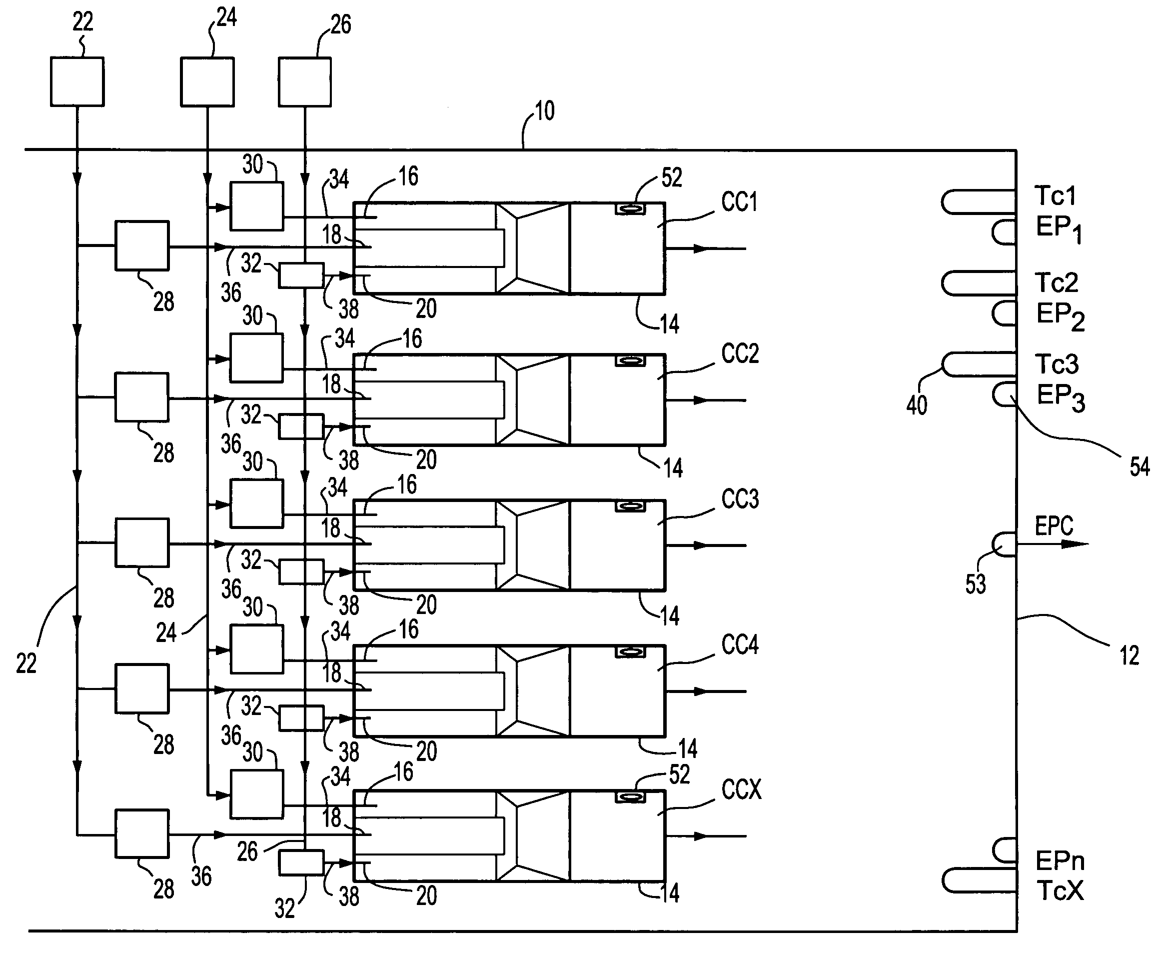
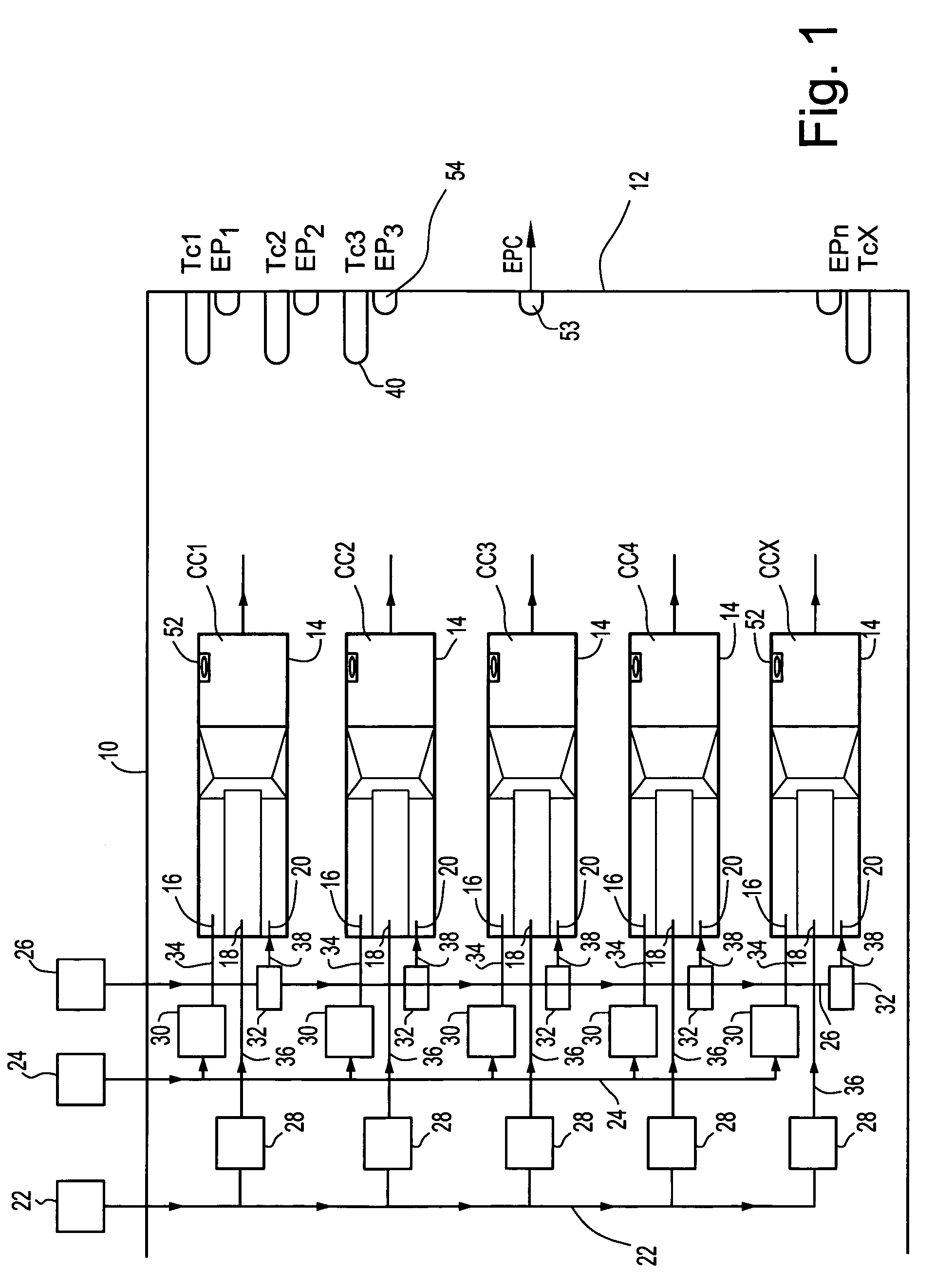
[0020]A system and method has been developed tuning a gas turbine to increase its efficiency. In general, an efficient gas turbine is one which has the least nitrous oxides, the least amount of unburned hydrocarbons, and the least amount of carbon monoxide for a specified energy output. To tune the gas turbine, it is desirable that the fuel flow to each combustion chamber in the gas turbine be well balanced relative to the remaining combustion chambers.

[0021]The system and method tunes each of the multiple combustion chambers such that no specific combustion chamber has a rich or lean air-fuel mixture ratio. It is preferably that the air-fuel mixture in each chamber be within about one percent (1%) of the remaining combustion chambers. The chambers are tuned such that the air-fuel mixture for each chamber is moved towards an average air-fuel mixture for all combustion chambers.

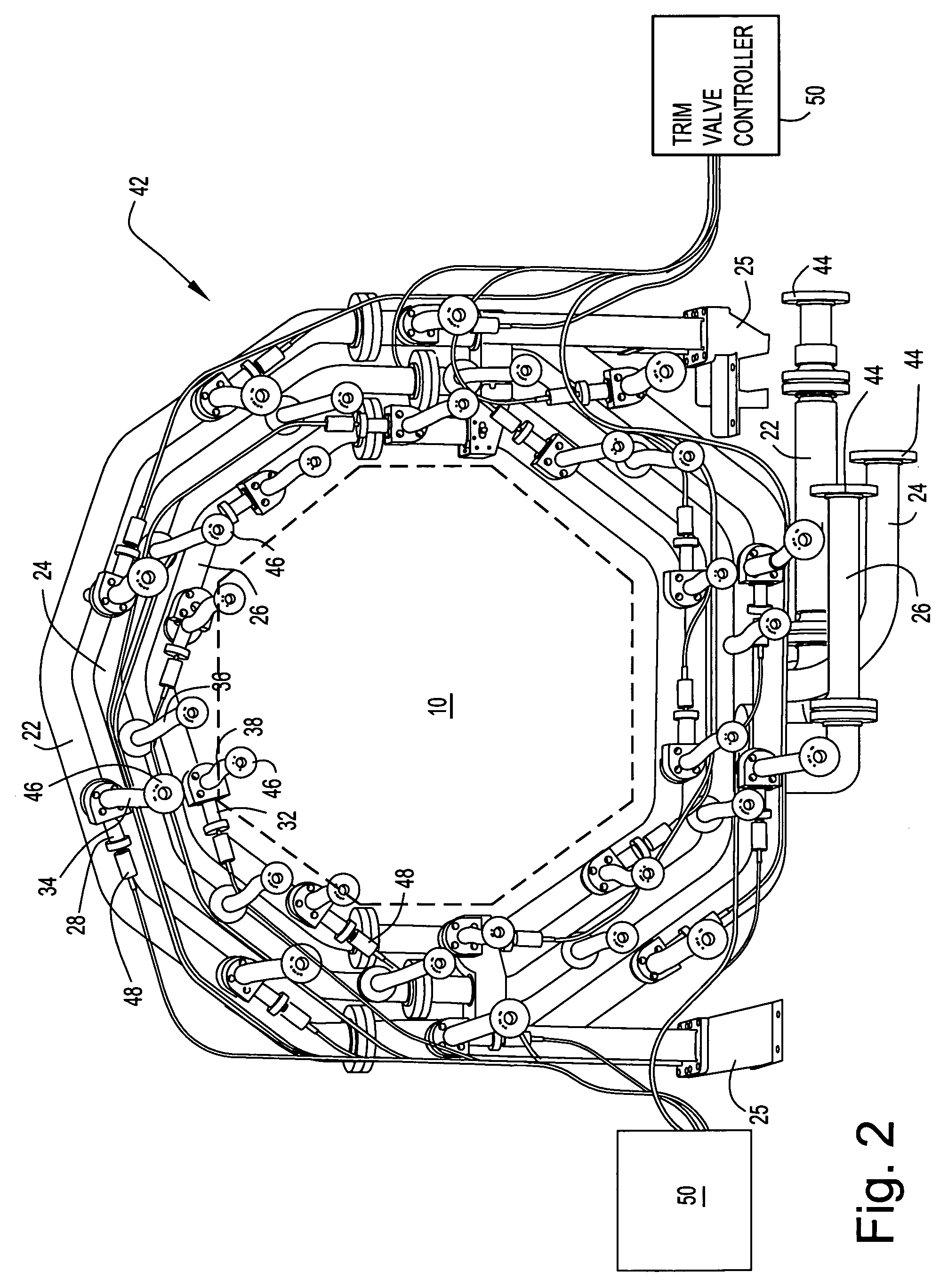
[0022]Each nozzle may have its own fuel control valve to control the fuel flowing to the nozzles. To minimi...


PUM


Abstract

A gas turbine combustion system having: a plurality of combustion chambers; a plurality of fuel nozzles for each of combustion chamber; a plurality of manifolds for supplying fuel to at least one fuel nozzle in each of the combustion chambers; each of the manifolds having fuel trim control valves for the fuel nozzles, wherein the fuel trim control valves are mounted on the multiple manifolds for metering the fuel to the fuel nozzles in the combustion chambers, and a trim valve controller automatically actuates one or more of the fuel trim valves to adjust fuel to the fuel nozzles based on gas turbine operating conditions.

Description

BACKGROUND OF THE INVENTION[0001]This invention relates to actuating fuel trim valves in a gas turbine applied to tune each combustion chamber. In particular, the invention relates to a system and method for automatically actuating fuel trim valves to a plurality of combustion chambers.[0002]Combustors in industrial gas turbines have a plurality of combustion chambers arranged around a turbine casing. High pressure air from the compressor flows into the chambers where the air is mixed with fuel. Fuel is injected into the chambers through nozzles. Hot gases generated by the combustion of the air and fuel mixture flow from the combustion chambers into the turbines which generally include a high-pressure turbine to drive the compressor and a low-pressure turbine to provide output power.[0003]Each combustion chamber defines a generally cylindrical combustion zone. Upstream of the combustion zone, the chambers each have a plurality of fuel nozzles that inject fuel into the zone. Fuel flo...

Claims


Application Information

Patent Timeline
Patent Type & Authority Patents(United States)
IPC IPC(8): F02C7/22F02C9/26
CPCF02C7/222F02C7/228F02C9/266F23N5/003F23R3/28F23N2037/02F23N2041/20F23N2237/02F23N2241/20
Inventor KOTHNUR, VASANTH SRINIVASASRINIVASAN, SHIVAKUMAR
Owner GENERAL ELECTRIC CO
Why Eureka
Try Eureka