Image processing device and method
a processing device and image technology, applied in the field of image processing devices and methods, can solve the problems of not being able to meet the encoding format of a high compression rate, not being able to meet the code quantity (bit rate) that is lower, etc., and achieve the effect of suppressing the deterioration of the control accuracy of data in the upper hierarchy, lowering the control accuracy of data in the lower hierarchy, and suppressing the deterioration of the control accuracy of slice division
- Summary
- Abstract
- Description
- Claims
- Application Information
AI Technical Summary
Benefits of technology
Problems solved by technology
Method used
Image
Examples
first embodiment
1. First Embodiment
Image Encoding Device of AVC Encoding Format
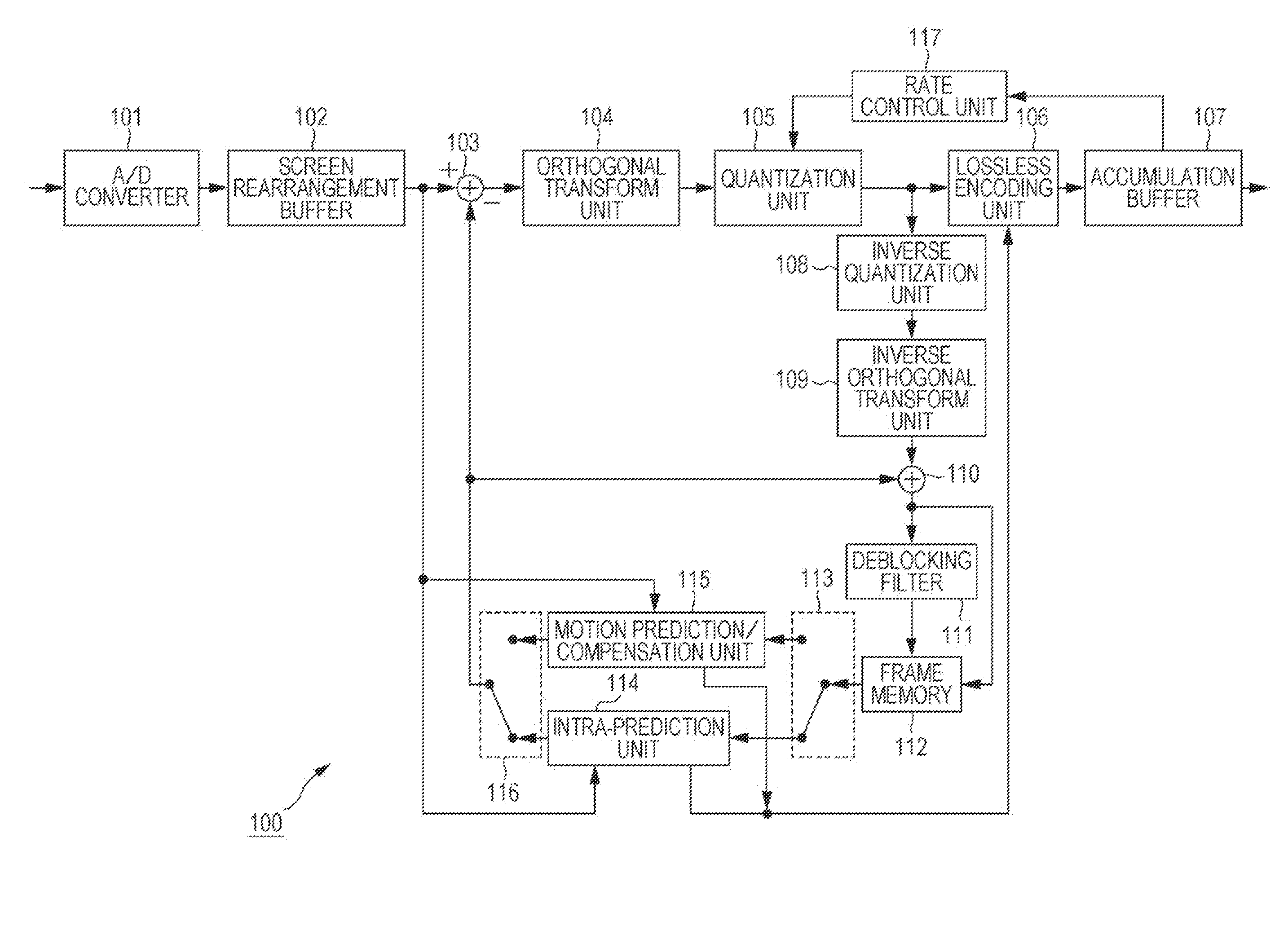
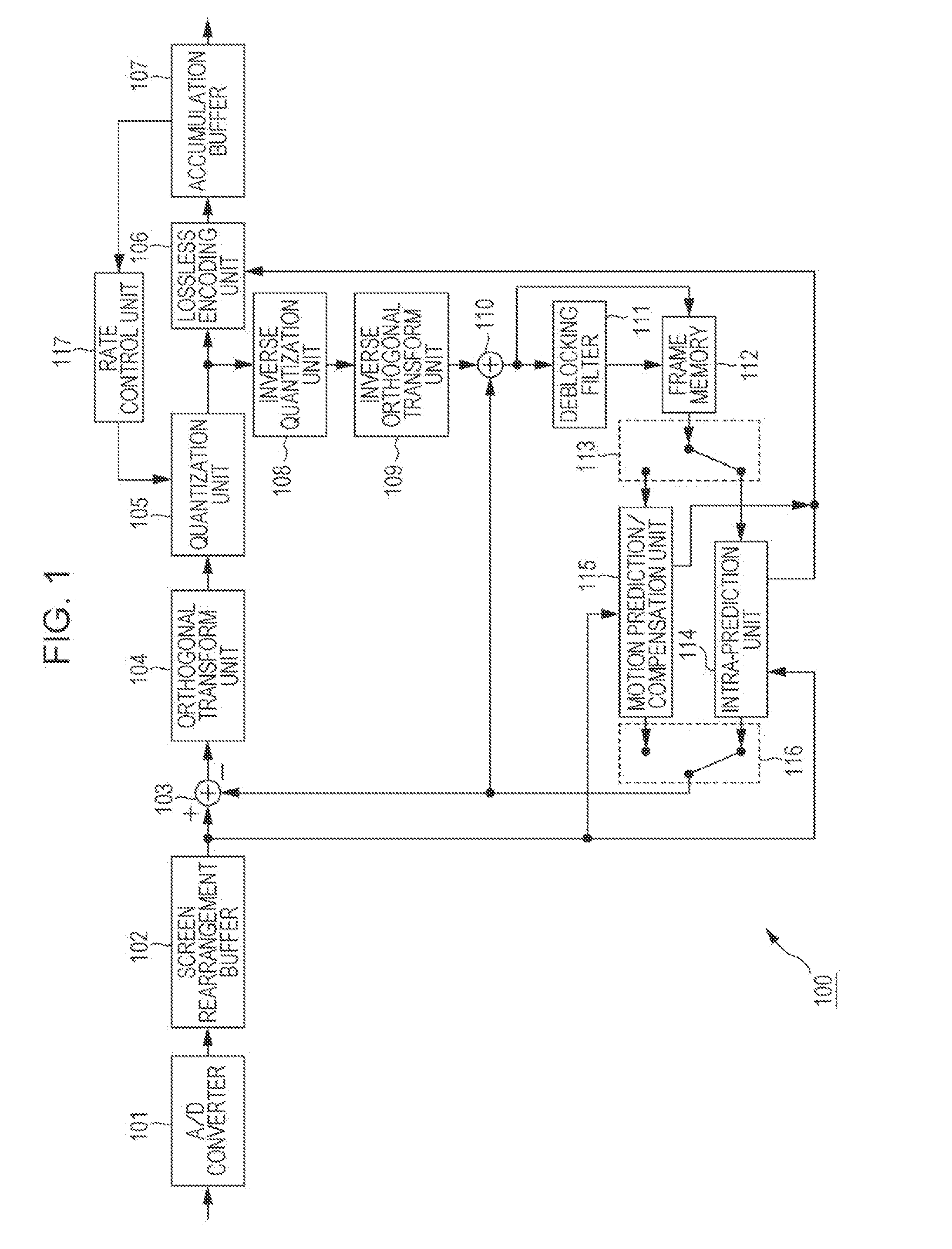
[0079]FIG. 1 shows a configuration of an embodiment of an image encoding device that encodes images in an encoding format of H.264 and MPEG (Moving Picture Experts Group) 4 Part 10 (AVC (Advanced Video Coding)).
[0080]The image encoding device 100 shown in FIG. 1 is a device that encodes and outputs images in an encoding format based on the AVC standard. As shown in FIG. 1, the image encoding device 100 has an A / D converter 101, a screen rearrangement buffer 102, an arithmetic operation unit 103, an orthogonal transform unit 104, a quantization unit 105, a lossless encoding unit 106, and an accumulation buffer 107. In addition, the image encoding device 100 has an inverse quantization unit 108, an inverse orthogonal transform unit 109, an arithmetic operation unit 110, a deblocking filter 111, a frame memory 112, a selection unit 113, an intra-prediction unit 114, a motion prediction / compensation unit 115, a selection uni...
second embodiment
2. Second Embodiment
Image Decoding Device
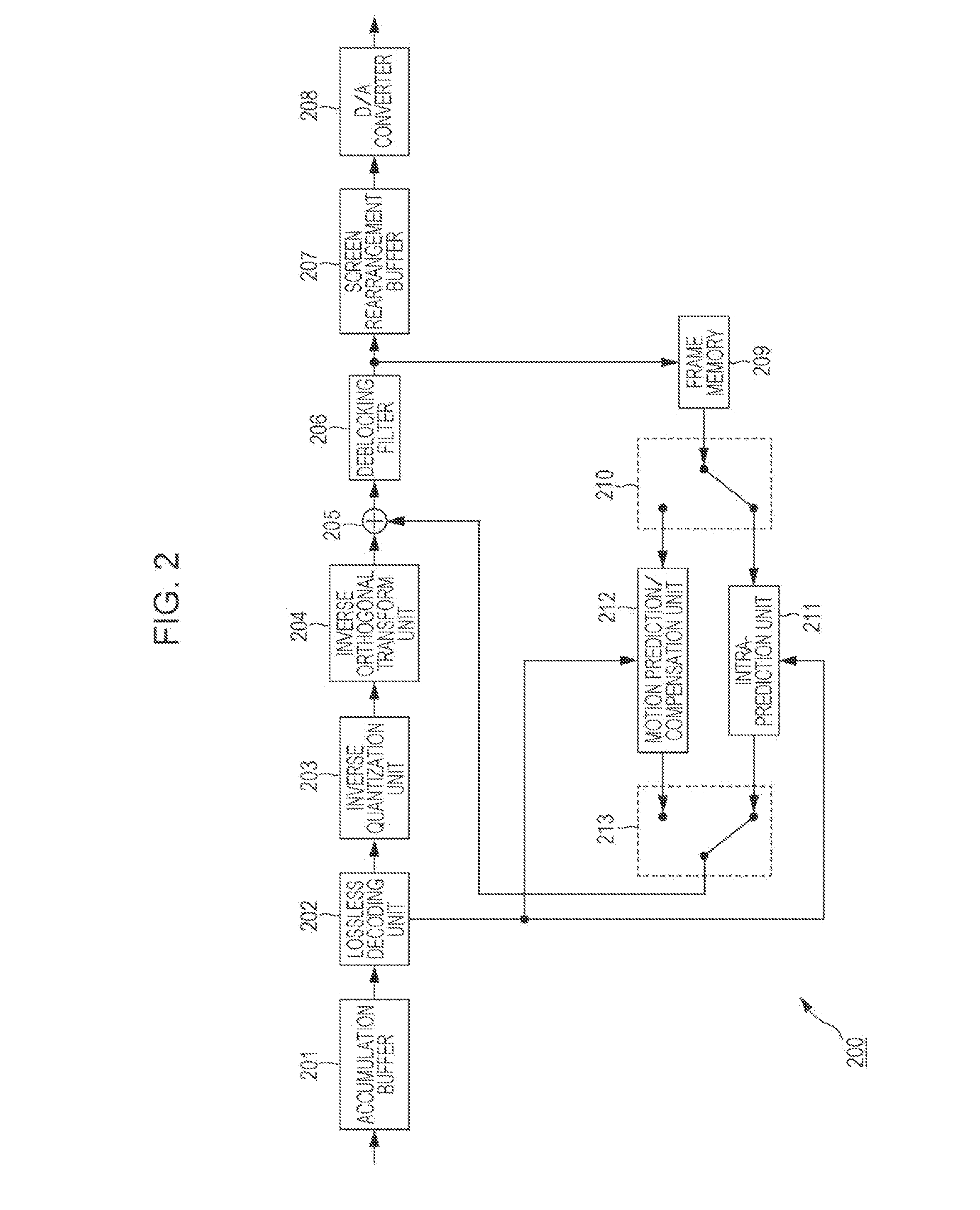
[0272]FIG. 17 is a block diagram showing a principal configuration example of an image decoding device. The image decoding device 400 shown in FIG. 17 is basically the same device as the image decoding device 200 of FIG. 2, and decodes encoded data that is obtained by encoding image data.
[0273]The image decoding device 400 shown in FIG. 17 is a decoding device corresponding to the image encoding device 300 of FIG. 7. Encoded data that has been encoded by the image encoding device 300 is supplied to the image decoding device 400 via an arbitrary path, for example, a transmission path, a recoding medium, or the like and then decoded.
[0274]The image decoding device 400 has an accumulation buffer 401, a lossless decoding unit 402, an inverse quantization unit 403, an inverse orthogonal transform unit 404, an arithmetic operation unit 405, a loop filter 406, a screen rearrangement buffer 407, and a D / A converter 408 as shown in FIG. 17. In additio...
third embodiment
3. Third Embodiment
[0330]A series of processes described above can be executed by hardware, or software. In such a case, for example, a personal computer as shown in FIG. 21 may be configured.
[0331]In FIG. 21, a CPU (Central Processing Unit) 501 of the personal computer 500 executes various processes according to a program stored in a ROM (Read Only Memory) 502, or a program loaded on a RAM (Random Access Memory) 503 from a storage unit 513. The RAM 503 appropriately stores data, or the like, necessary for the CPU 501 to execute various processes.
[0332]The CPU 501, the ROM 502, and the RAM 503 are connected to one another via a bus 504. An input and output interface 510 is also connected to the bus 504.
[0333]The input and output interface 510 is connected to an input unit 511 including a keyboard, a mouse, and the like, an output unit 512 including a display such as a CRT (Cathode Ray Tube), an LCD (Liquid Crystal Display), or the like, a speaker, and the like, a st...
PUM
 Abstract
Description
Claims
Application Information
 - R&D
- Intellectual Property
- Life Sciences
- Materials
- Tech Scout
- Unparalleled Data Quality
- Higher Quality Content
- 60% Fewer Hallucinations
Browse by: Latest US Patents, China's latest patents, Technical Efficacy Thesaurus, Application Domain, Technology Topic, Popular Technical Reports.
© 2025 PatSnap. All rights reserved.Legal|Privacy policy|Modern Slavery Act Transparency Statement|Sitemap|About US| Contact US: help@patsnap.com


