Liquid ejection apparatus

a technology of liquid ejection and ejection chamber, which is applied in the direction of printing, etc., can solve the problems of the closing of the air discharge opening, and the deterioration of the performance of the humidifier itself, so as to prevent the deterioration of the humidification function

Active Publication Date: 2012-06-28
BROTHER KOGYO KK
View PDF8 Cites 27 Cited by
  • Summary
  • Abstract
  • Description
  • Claims
  • Application Information

AI Technical Summary

Benefits of technology

[0006]The present invention was made in view of the above-described background factors. It is therefore an object of the invention to provide a liquid ejection apparatus in

Problems solved by technology

Therefore, the liquid is likely to flow into the air discharge opening, together with discharge of the air from the ejection space, and the liquid having flowed into the air discharge opening could cause c

Method used


Image

  • Liquid ejection apparatus
  • Liquid ejection apparatus
  • Liquid ejection apparatus

Examples


first embodiment

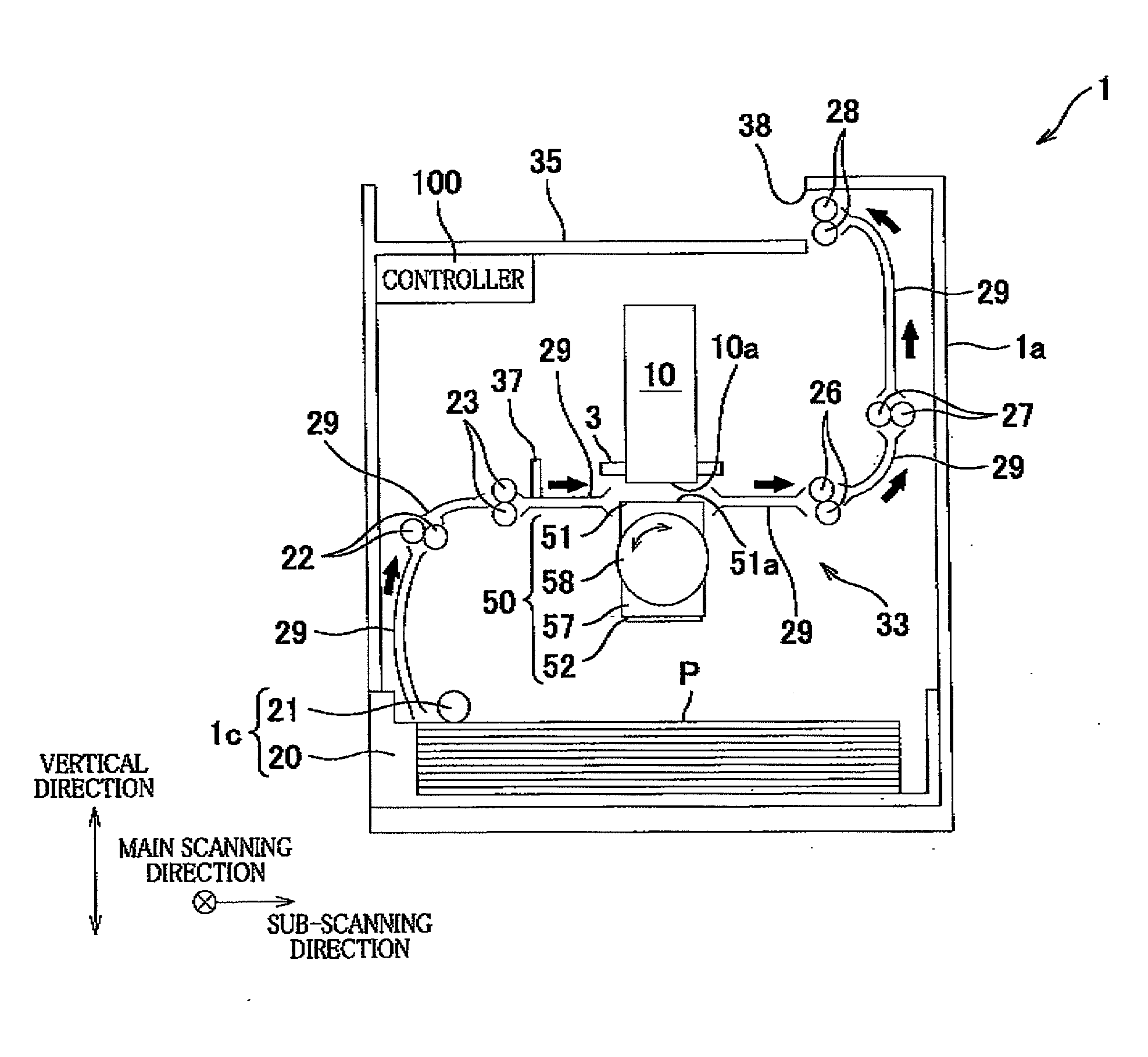
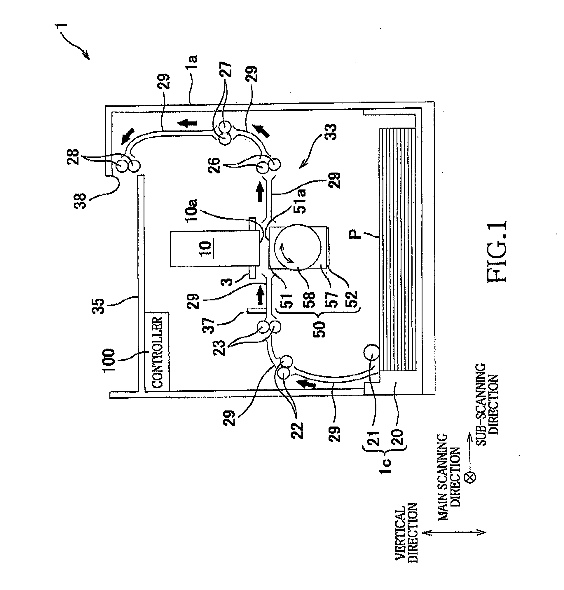
[0024]FIG. 1 shows an overall construction of an inkjet printer 1 constructed according to the invention.

[0025]The printer 1 has a generally rectangular parallelepiped-shaped housing body 1a. A sheet discharge portion 35 is provided on a top plate of the housing body 1a. In a space defined in the housing body 1a, there is a sheet conveyance path along which a recording medium in the form of a sheet P is to be conveyed, as indicated by thick arrows in FIG. 1, from a sheet supply unit 1c toward the sheet discharge portion 35.

[0026]The housing body 1a accommodates therein a head (liquid ejection head) 10, a sheet conveying mechanism 33, a support / cap unit 50, a humidifier unit 60 (see FIG. 5), a liquid suction unit 70 (see FIG. 5), a cartridge (not shown) and a controller 100. The sheet conveying mechanism 33 is configured to convey the sheet P such that the sheet P passes a position that is opposed to a liquid ejection surface 10a of the head 10. The support / cap unit 50 is disposed in...

second embodiment

[0089]In the present second embodiment, as shown in FIG. 9, the cap fixing member 57 is provided with, in place of the recessed member 52, the opposed portion 53 without the peripheral portion 54. The support / cap unit 50 includes the movable peripheral body 500 in place of the rotary-body elevating mechanism 56.

[0090]In the first embodiment, the opposed portion 53 is provided with the flow restraining plates 59 as the protrusion walls. However, in the present second embodiment, the opposed portion 53 is provided with, in place of the flow restraining plates 59, a frame-like flow restraining plate 85 as the protrusion wall which protrudes upwardly from the opposed portion 53 and which surrounds the liquid discharge area 81. The plate-like cap tip 90 is provided in the liquid discharge area 81 of the opposed portion 53, for increasing efficiency of suction of the ink by the suction pump 77. It is noted that, in the present second embodiment, the opposed portion 53 is slightly larger t...

third embodiment

[0101]In the present third embodiment, the peripheral recess 86 is provided in the opposed portion 53 such that the liquid discharge area 81 is surrounded by the peripheral recess 86. When the liquid suction is being carried out, the ink depositing on the liquid discharge area 81 is caused, by movement of the wiper 591 in the main scanning direction, to flow down to the bottom surface 86b of the peripheral recess 86 via an inside surface 86a of the peripheral recess 86, i.e., via a side surface of the peripheral recess 86, which is located on the side of the liquid discharge area 81.

[0102]The liquid suction openings 74 are provided in respective portions of the bottom surface 86b of the peripheral recess 86, which are opposite to each other in the main scanning direction. The ink flowing onto the bottom surface 86b is sucked by activation of the liquid suction unit 70, and is caused to flow out of the ejection space S1 via the liquid suction openings 74. In the present third embodim...


PUM


Abstract

A liquid ejection apparatus including: a liquid ejection head that ejects ink through liquid ejection openings in a liquid ejection surface of the head, a cap device that establishes a sealing state, such that an ejection space opposed to the liquid ejection surface is sealed from an exterior space by the cap device, an air introduction opening and an air discharge opening that are located in the cap device, and a humidifier that supplies an humidified air into the ejection space through the air introduction opening and that discharges an air from the ejection space through the air discharge opening. The air discharge opening opens in an area other than a liquid discharge area onto which the ejected liquid is to be discharged. The apparatus further includes a flow restrainer that restrains the liquid discharged onto the liquid discharge area, from flowing to the air discharge opening.

Description

CROSS REFERENCE TO RELATED APPLICATION[0001]This application claims priority from Japanese Patent Applications No. 2010-293917 filed on Dec. 28, 2010, the disclosure of which is herein incorporated by reference in their entirety.BACKGROUND OF THE INVENTIONField of the Invention[0002]The present invention relates to a liquid ejection apparatus for ejecting a liquid such as ink.[0003]A liquid ejection apparatus is provided with a head having a liquid ejection surface defining liquid ejection openings through which a liquid such as ink is to be ejected. If a long time has elapsed without the liquid being ejected through the liquid ejection openings, the liquid in the vicinity of each of the liquid ejection openings is likely to be evaporated whereby viscosity of the ink could be increased. The increased viscosity of the ink could cause clogging of the liquid ejection openings. There is known a technique for preventing the clogging of the liquid ejection openings.[0004]In the known tech...

Claims


Application Information

Patent Timeline
IPC IPC(8): B41J2/165
CPCB41J2/16508B41J2/165
Inventor TAIRA, HIROSHI
Owner BROTHER KOGYO KK
Why Eureka
Try Eureka