
Shrouded-plasma process and apparatus for the production of metastable nanostructured materials

a nanostructured material and nano-structure technology, applied in the field of material processing, can solve the problems of not all conversion and no attempt to obtain a completely uniform coating structure, and achieve the effects of enhancing sinterability, promoting densification, and efficient processing of metastable materials

Inactive Publication Date: 2007-03-01
RUTGERS THE STATE UNIV
View PDF25 Cites 63 Cited by
  • Summary
  • Abstract
  • Description
  • Claims
  • Application Information

AI Technical Summary

Benefits of technology

[0053] As-synthesized RCP-derived material typically has a homogeneous metastable structure, which may take the form of an extended solid solution phase, a metastable intermediate phase, or a non-crystalline (amorphous) phase. This is significant, since subsequent post-annealing to induce a metastable-to-stable phase transformation necessarily generates a completely uniform nanocrystalline (one phase) or nanocomposite (two or more phases) structure, depending on the initial composition.
[0054] When a metastable multi-component ceramic is post-annealed, the final result depends on the selected temperature. If the selected temperature is just sufficient to cause diffusion, then phase decomposition tends to follow a path through a series of metastable intermediate states, prior to the formation of the final equilibrium state. For example, FIG. 5 shows the stages in the thermal decomposition of a metastable ZrO2-base powder, leading to the formation of a “triphasic nanocomposite” structure. Similar results have been obtained for other post-annealed RCP-processed ceramics.
[0055] Investigation on the consolidation of a melt-quenched metastable ceramic powder has demonstrated that the initiation of a metastable-to-stable phase decomposition during sintering has the effect of promoting densification at relatively low temperatures. The effect is particularly striking during pressure-assisted sintering of a powder compact at a temperature where the material is just beginning to decompose, since the material also displays superplasticity. The effect not only enhances sinterability, but also enables the resulting nanocomposite body to be superplastically formed into any desired shape or form.
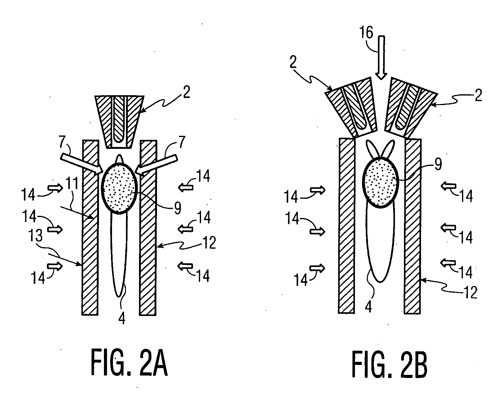
[0056] Over the past two years, we have investigated various designs of shrouded-plasma reactors, in which a high enthalpy plasma acts as heat source and a powder, slurry or aerosol serves as feed material. Since a powder injection unit is an integral part of many of today's commercial plasma spray systems, the attachment of a heat-resistant shroud 12 to the plasma torch 2 is all that is needed to ensure complete melt-homogenization of all the feed particles in a single pass through the reactor, prior to water-quenching to obtain a uniform metastable powder product. This has proved to be the case, irrespective of the type of radial or axial powder delivery unit used in conjunction with the shrouded-plasma reactor (see FIG. 2A). However, because of recent advances in the design of an axially-fed DC triple-arc plasma system, FIG. 2B, this arrangement appears to be best-suited for the high rate production of metastable powders and deposits.
[0057] In systems designed for use of an aerosol feed, controlled injection of the feed material directly into the plasma flame 4 is a challenge, since varying pressures and temperatures exist within the tubular reactor. Moreover, the aerosol particles must remain in the hot zone (reaction zone 9) for a sufficient time (residence time) to complete the desired thermo-chemical reactions, since otherwise a heterogeneous powder product is obtained. In practice, this is best accomplished by injecting the aerosol precursor directly into the reaction zone 9 in the form of three symmetrical feed streams, using conventional pressure- or ultrasonic atomizers. For the high rate production of a metastable powder or deposit, the pressure-atomization method is preferred. On the other hand, for the low rate deposition of a metastable thin film, the ultrasonic-atomization method is favored. In both cases, precise convergence of the three aerosol-jet streams within the plasma-reaction zone 9, as shown in FIGS. 6A and 6B, is the key to the efficient processing of metastable material.
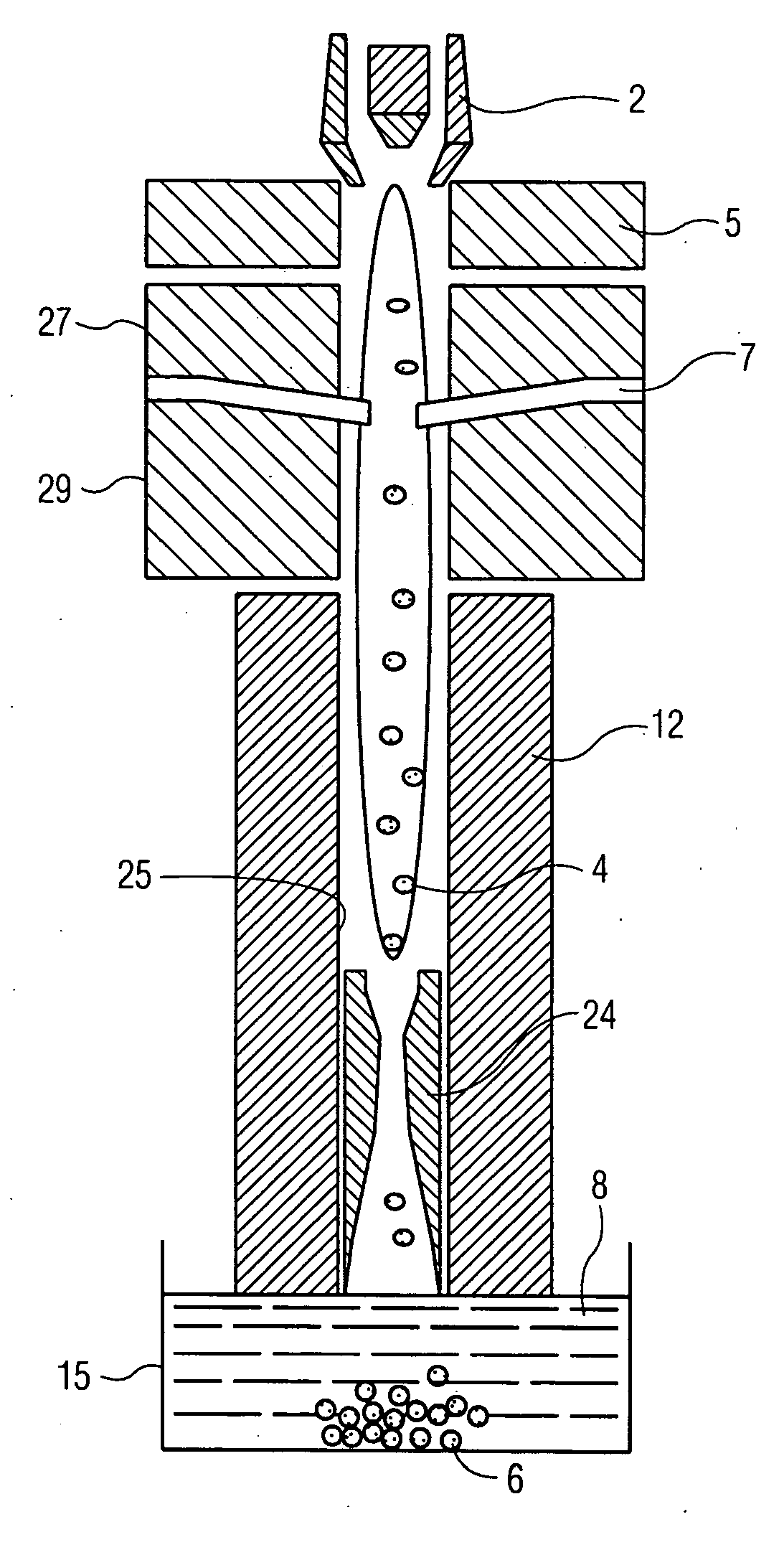
[0058] A schematic of the basic design of a shrouded-plasma reactor is shown in FIG. 7. Its modular construction facilitates changes in critical processing parameters, such as stand-off distance between the plasma torch or plasma gun 2 and aerosol-injection ports 7, feed particle residence time in the reaction zone 9, and temperature gradient within an extended plasma flame 4. Because of its simplicity and versatility, collection of the as-synthesized nanoparticles 6 in a bath of cold water 8 is an attractive option. However, in situations where chemical reactions occur between the rapidly-quenched nanoparticles 6 and the quenching medium (water / steam), then a “dry collection” method must be used. This has proved to be case in the processing of some oxide ceramics, such as Y2O3, which are highly susceptible to hydrolysis. In such cases, the shrouded-plasma reactor is contained within a stainless-steel chamber 30, which collects the nanoparticles 6 on its chilled walls. Another requirement is the use of an organic-base solvent instead of a water-base solvent, so as to avoid introducing water vapor along with the precursor feed streams 7, 16. Experience has shown that methyl alcohol is a suitable solvent for many inorganic salts. However, in some cases, a hydrocarbon solvent, such as hexane, must be used. Whatever the details, it is clear that the aerosol formulation can be adjusted to yield nanopowders of specific compositions, without introducing undesirable impurities.

Problems solved by technology

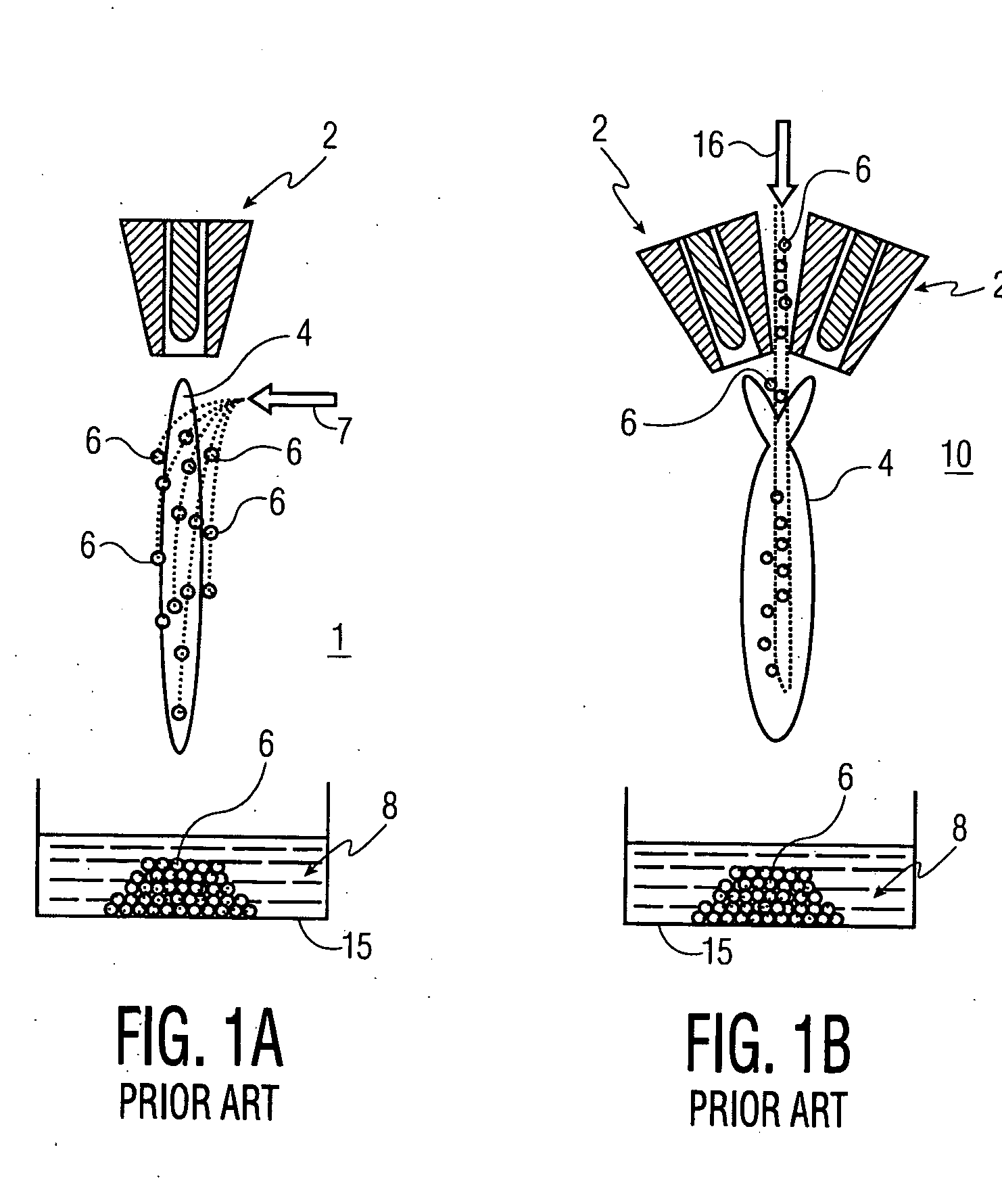
It was observed that a single melt-quenching treatment using this method did not convert all the feed particles 6 into a metastable powder product.
In all such cases, however, no attempt is made to obtain a completely uniform coating structure, nor is this possible by injecting an aerosol feed stream into a conventional non-shrouded plasma flame.

Method used


Image

  • Shrouded-plasma process and apparatus for the production of metastable nanostructured materials
  • Shrouded-plasma process and apparatus for the production of metastable nanostructured materials
  • Shrouded-plasma process and apparatus for the production of metastable nanostructured materials

Examples


example 1

[0071] Synthesis of YAG powder—A starting solution was prepared by dissolving 139 g of yttrium nitrate (Y(NO3)3.xH2O)+316 g of aluminum nitrate (Al(NO3)3.9H2O) in 500 ml of deionized water. The solution was fed at a rate of 15 cc / min to an atomizer, using a peristaltic pump. Atomization was achieved by forcing the liquid under a pressure through a rectangular nozzle (0.5 mm×1.0 mm). Argon at a pressure of 10 psi was used as atomizing gas, and mixing of the solution and argon to form an aerosol was achieved inside the nozzle.

[0072] A Sulzer-Metco 9 MB plasma torch 2, operating with a Ar-10% H2 gas mixture, was used to obtain 30 kW power. A water-cooled copper shroud, attached to the plasma torch, and cooled internally with flowing argon at a pressure of 60 psi, was used as a particle reactor. The aerosol was delivered to the plasma in the manner depicted in FIG. 3A. The lower end of the tubular shroud 12 was partially immersed (about 3.0 cm) in a 100 liter drum 15 of cold water 8 to...

example 2

[0074] Influence of precursor concentration and flow rate—Starting solutions were prepared and processed, as in Example 1, but using different precursor concentrations and flow rates. Using a high precursor concentration and flow rate, FIG. 10A, the effect is to generate two phases: a major amorphous phase and a minor crystalline phase, which indexes as cubic YAG. In contrast, using a low precursor concentration and flow rate, the effect is to reverse the product mix, FIG. 10B; a major crystalline phase and a minor amorphous phase. On the basis of these two results, it appears that the critical parameter determining the relative abundance of the amorphous and crystalline phases in the product powder is the precursor flow rate, with the precursor concentration playing a lesser role. To validate this conclusion, experiments are now being conducted under widely different flow rate conditions, keeping the precursor concentration constant, and vice versa.

example 3

[0075] Synthesis of BN powder—A starting solution was prepared by dissolving 150 g of H3BO3 or B2O3.3H2O in 300 ml of methyl alcohol (CH3OH). The material was atomized, as in Example 1, using N2 as atomizing gas. An N2-10% H2 mixture was used as plasma gas, giving 50 kW power output. Nitrogen at a pressure of 60 psi was used as cooling gas in the water-cooled copper shroud.

[0076] An X-ray diffraction pattern of the as-synthesized powder 6 is shown in FIG. 11A for powder 6 quenched in water, and in FIG. 11B for powder collected from the sidewalls of nozzles (not shown) as described above. The crystalline peaks correspond to B2O3 and cubic-BN, with an unidentified broad amorphous peak. A noteworthy result is the appearance of cubic-BN, which is a metastable polymorph of BN, typically produced only under high pressure / high temperature processing conditions, and then only in the presence of a liquid metal catalyst. The fact that it can be produced by plasma processing at near-ambient p...


PUM

PropertyMeasurementUnit
sizeaaaaaaaaaa
sizeaaaaaaaaaa
particle sizeaaaaaaaaaa

Abstract

A method and apparatus for producing metastable nanostructured materials employing a ceramic shroud surrounding a plasma flame having a steady state reaction zone into which an aerosol or liquid jet of solution precursor or powder material is fed, causing the material to be pyrolyzed, melted, or vaporized, followed by quenching to form a metastable nanosized powder that has an amorphous (short-range ordered), or metastable microsized powder that has a crystalline (long-range ordered) structure, respectively.

Description

RELATED APPLICATIONS [0001] This application is a Continuation-In-Part of U.S. patent application Ser. No. 11 / 259,299, filed on Oct. 26, 2005, co-pending herewith, which Application is a Division of Ser. No. 10 / 049,709, filed Jul. 16, 2002, which is a 371 of PCT / US00 / 22811 filed Aug. 18, 2000, which claims the benefit of Provisional Ser. No. 60 / 149,539 filed Aug. 18, 1999.GOVERNMENT LICENSE RIGHTS [0002] The U.S. Government has a paid-up license in this invention and the right in limited circumstances to require the patent owner to license others on reasonable terms as provided for by the terms of Grant Number N00014-01-1-0079 awarded by the Office of Naval Research.FIELD OF THE INVENTION [0003] The present invention relates generally to the field of plasma processing of materials, and more particularly to the plasma spraying of protective coatings on bulk materials. BACKGROUND OF THE INVENTION [0004] Known plasma-spray systems typically use an aggregated powder as feed material, an...

Claims


Application Information

Patent Timeline
Patent Type & Authority Applications(United States)
IPC IPC(8): C03B19/00C03B19/10C03B37/018C03B37/01
CPCB22F9/28H05H1/48B22F2999/00B82Y30/00C01B13/185C01B13/34C01B21/064C01B25/45C01F17/0025C01G3/00C01G19/00C01G25/00C01G25/02C01G53/00C01P2002/32C01P2002/72C01P2004/03C01P2004/04C01P2004/64C03B19/102C04B35/62665C04B2235/3222C04B2235/3225C04B2235/3246C04B2235/3279C04B2235/3286C04B2235/3293C04B2235/386C04B2235/441C04B2235/447C04B2235/5454H05H1/42B22F9/30C01P2004/62C01P2004/45C01P2002/77C01G49/00C01P2002/02C01P2002/52B22F2202/13C01F17/34H01J37/32
Inventor KEAR, BERNARD H.SHUKLA, VIJAYSADANGI, RAJENDRA K.
Owner RUTGERS THE STATE UNIV
Learn More