Liquid-jet/liquid droplet initiated plasma discharge for generating useful plasma radiation

a plasma radiation and liquid droplet technology, applied in the field of plasma discharge radiation sources, can solve the problems of limited lifespan of sources, and reducing the operating lifespan of these sources, so as to reduce damage to related optic components

Inactive Publication Date: 2006-02-14
UNIV OF CENT FLORIDA RES FOUND INC
View PDF20 Cites 66 Cited by
  • Summary
  • Abstract
  • Description
  • Claims
  • Application Information

AI Technical Summary

Benefits of technology

[0008]A third objective of the invention is to provide a plasma discharge source(s) for generating emissions in the VUV, EUV and X-ray spectral region resulting in reduced damage on related optic components caused the emission of debris.
[0009]A fourth objective of the invention is to provide a plasma discharge source(s) for generating emissions in the VUV, EUV and X-ray spectral regions that reduces debris generation from the source(s). Because the plasma can be generated in an unconfined region, there will be no debris generated from a confining medium such as a narrow capillary.
[0010]A fifth objective of the invention is to provide a plasma discharge source(s) for generating emissions in the VUV, EUV and X-ray spectral regions that has increased longevity over existing gas formed plasma discharge sources.
[0012]A seventh objective of the invention is to provide a plasma discharge source(s) for generating emissions in the VUV, EUV and X-ray spectral region where the plasma can be located in a very low-pressure region so as to avoid absorption of the useful radiation by a surrounding gaseous medium.
[0015]Preferred embodiments of the invention include systems of using a liquid jet stream within a vacuum region to initiate a plasma discharge for generating emissions in the VUV, EUV or X-ray spectral regions. The liquid jet stream can be composed of the constituent radiating material, as well as other useful components, and would be directed between two electrodes. The jet stream can serve as the initial conducting path between the electrodes when a high voltage is applied between the electrodes. The initial current between the electrodes can occur within the liquid jet stream, thereby heating the material within the jet, causing it to vaporize and convert to an expanding gaseous plasma discharge. The discharge current can be operated for a duration of up to approximately a few microseconds. The diameter of the jet stream can be determined by the quantity of vaporized ions desired to be within the plasma discharge as it expands. The velocity of the jet stream can be of the order of approximately 50 m / sec, which can allow a pulse repetition frequency of the order of approximately 5 kHz to be used and still allow the jet stream to reform between pulses. The expanding ionized gas can be pumped out of the system between pulses, or collected on the surrounding collecting plates in situations in which the jet stream material consists of a vapor at room temperature instead of a gas. A pre-pulse can be advantageous in order to vaporize the liquid before the main current pulse is initiated.

Problems solved by technology

However, problems have occurred with these capillary discharge sources that have included but not limited to debris that also is emitted by the capillary discharge sources.
The debris has the result of reducing the operating lifespan of these sources since the debris has been known to damage the surrounding optics such as lens, and other optical components that are used with the capillary discharge sources.
In addition the interior walls of the capillary plasma discharge sources constantly wear down during operation which results in a limited lifespan for the sources.
Although the '613 patent reduces the effects of the debris, it still does not reduce nor eliminate the actual generation of the debris from the plasma discharge sources.
However, exploding wires create other problems.
For example, the wires are not reusable and can also generate debris.

Method used


Image

  • Liquid-jet/liquid droplet initiated plasma discharge for generating useful plasma radiation
  • Liquid-jet/liquid droplet initiated plasma discharge for generating useful plasma radiation
  • Liquid-jet/liquid droplet initiated plasma discharge for generating useful plasma radiation

Examples


first preferred embodiment

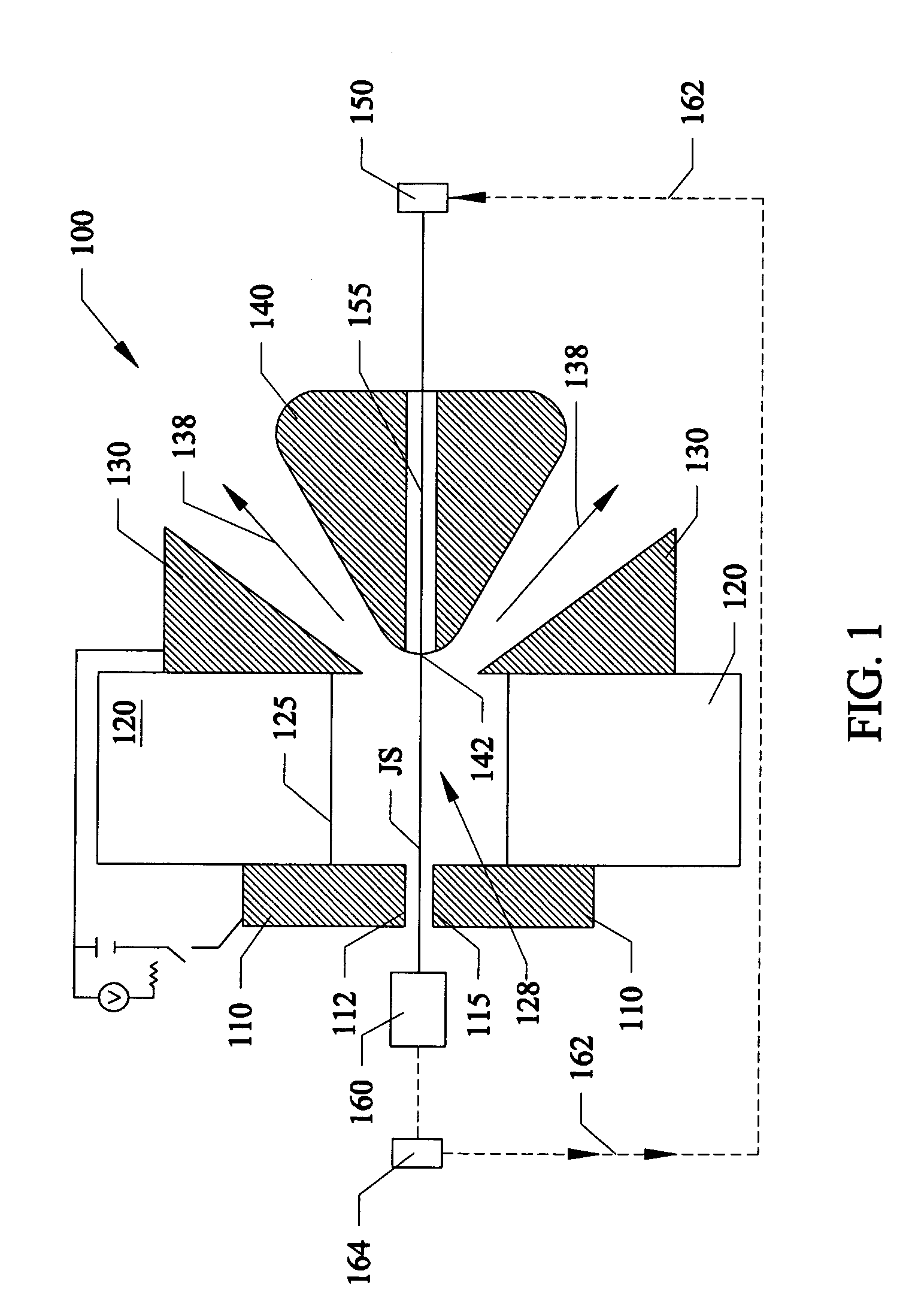
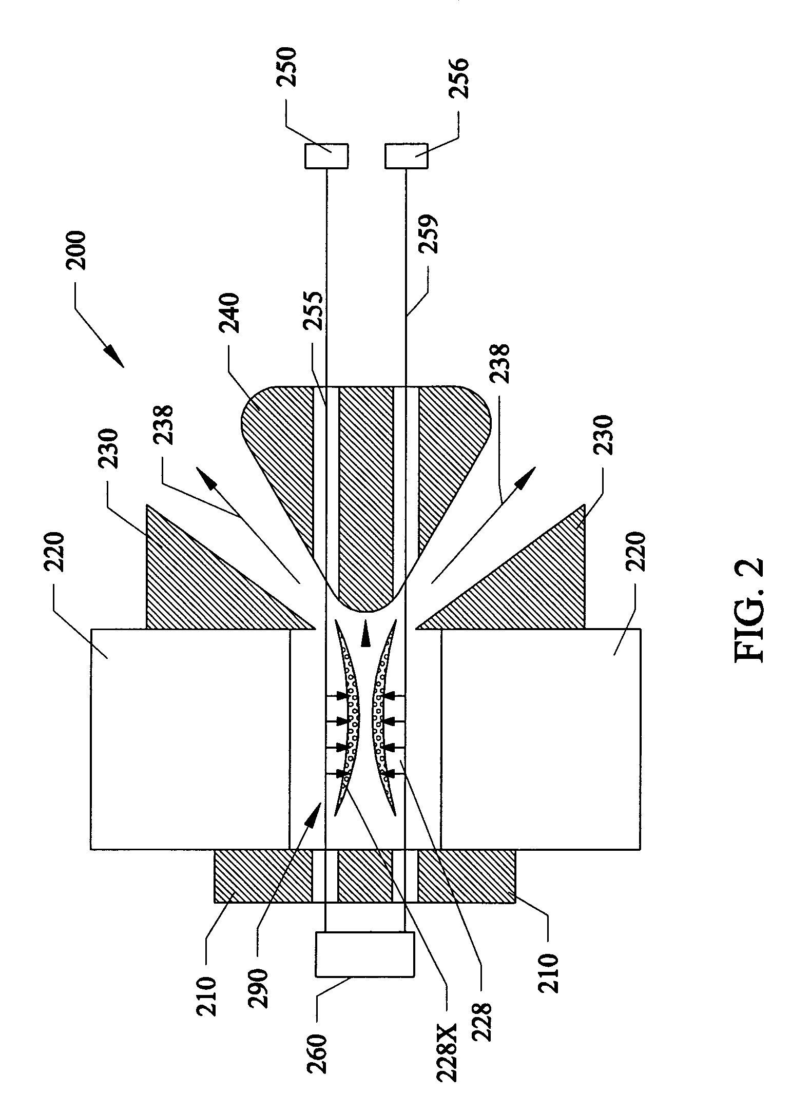
[0027]FIG. 1 shows a cross-sectional view of a first preferred embodiment 100 of an inertially confined liquid jet discharge source. 110 refers to electrodes having a space 115 formed there between. An electrode 110, such as a metal electrode can function as an anode, and be to one side of an insulator 120, such as an electrically insulating or partially insulating insulator such as but not limited to an insulating material such as rubber, a ceramic, glass, and the like. On the opposite side of the insulator 120 can be a second electrode 130–140, such as a metal electrode that can function as a cathode. Either electrode 110, 130 / 140 can also function as an emitter or collector of the liquid jet. Electrode portion 140 can function like a debris blocker similar to those described in U.S. Pat. No. 6,232,613 to the same assignee as that of the subject invention, which is incorporated by reference. Liquid jet stream generating device 150 can be a pressurized metal or insulative liquid re...

second preferred embodiment

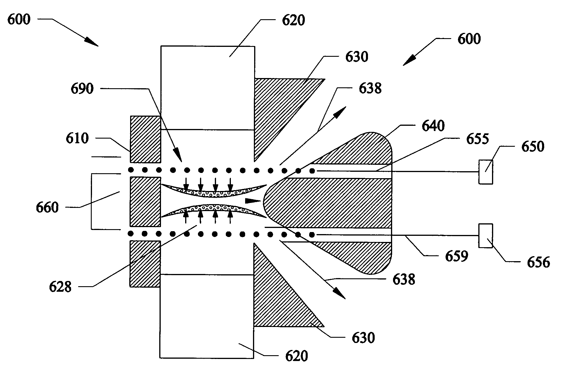
[0041]FIG. 2 shows a cross-sectional view of a second preferred embodiment 200 of a liquid jet pinch plasma discharge source with a cylindrical variant 228. Electrode (Anode) 210, insulator 220, electrode (cathode) 230, 240, and receptical 260 can be identical to the similarly labeled components in the embodiment of FIG. 1. In FIG. 2, there can be two or more liquid jet stream generating devices 250, 256, and two or more liquid jet injectors 255, 259 each similar to the liquid jet generating device (reservoir) 150, and jet injector 155 shown and described in FIG. 1. Alternatively, several liquid jet injectors can be run from a common liquid jet stream generating device.

[0042]The liquid jet injectors 255, 259 can be used to generate a continuous conductive liquid jet stream which provides a current path. In essence the current will run through the jet stream.

[0043]The functional description of all components of the source 200 in FIG. 2 can be identical to that those shown in FIG. 1. ...

third preferred embodiment

[0045]FIG. 3 shows a cross-sectional view of third preferred embodiment 300 of a jet pinch plasma discharge with a conical variant. Electrode (Anode) 310, insulator 320, electrode (cathode) 330 / 340, liquid jet steam generating devices 350, 356, liquid jet injectors 355, 359, and receptical 360 are each similar to the similarly labeled components in the preceeding embodiments.

[0046]Similar to the previous embodiments, the injectors 355, 359 can be used to generate a continuous conductive liquid jet stream which provides a current path.

[0047]The functional description of all the components in FIG. 3 are identical to those shown in FIG. 1. The function of the cylindrical sets of jets is the same as in the second embodiment (FIG. 2), except that the cylindrical plasma sheath is now a (slightly) conical plasma sheath. This slightly conical plasma sheath can be produced by a conical array of jet assemblies and receptical(s). The compressing sheath plasma can converge on itself in the same...


PUM


Abstract

Plasma discharge sources for generating emissions in the VUV, EUV and X-ray spectral regions. Embodiments can include running a current through liquid jet streams within space to initiate plasma discharges. Additional embodiments can include liquid droplets within the space to initiate plasma discharges. One embodiment can form a substantially cylindrical plasma sheath. Another embodiment can form a substantially conical plasma sheath. Another embodiment can form bright spherical light emission from a cross-over of linear expanding plasmas. All the embodiments can generate light emitting plasmas within a space by applying voltage to electrodes adjacent to the space. All the radiative emissions are characteristic of the materials comprising the liquid jet streams or liquid droplets.

Description

[0001]This invention relates to discharge sources, and in particular to methods and apparatus for using liquid jet streams or liquid droplets within spaces to form plasma discharge for generating debris free and debris reduced emissions in the VUV, EUV, and X-ray spectral regions, and this invention claims the benefit of priority to U.S. Provisional Application Ser. No. 60 / 305,334 filed Jul. 13, 2001, by the same inventors and assignee as the subject invention.BACKGROUND AND PRIOR ART[0002]Various types of plasma discharge radiation sources have been proposed over the years. For example, capillary plasma discharge sources generate emissions in various wavelengths, that have include the EUV spectral ranges. The capillary discharge sources generally require a discharge occurring as a consequence of inducing electrical current into a gas located in a bore within a cavity. However, problems have occurred with these capillary discharge sources that have included but not limited to debris...

Claims


Application Information

Patent Timeline
Patent Type & Authority Patents(United States)
IPC IPC(8): H01J7/24H05B31/26
CPCH05G2/003
Inventor SILFVAST, WILLIAM T.RICHARDSON, MARTIN C.
Owner UNIV OF CENT FLORIDA RES FOUND INC
Why Eureka
Try Eureka