Liquid ejection apparatus and image forming apparatus
a technology of liquid ejection and image forming, which is applied in the direction of printing, etc., can solve the problems of no disclosure of technology for improving the cleaning performance achieved by wiping, and inability to achieve high-quality printing. achieve the effect of effective cleaning operation, restore cleaning performance, and improve cleaning functions
- Summary
- Abstract
- Description
- Claims
- Application Information
AI Technical Summary
Benefits of technology
Problems solved by technology
Method used
Image
Examples
example 1
Mode Using Device for Identifying Amount of Wear of Wiper
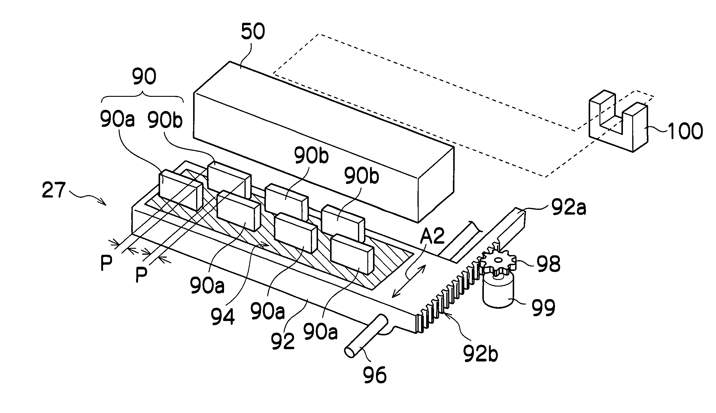
[0196] As a method for identifying the amount of wear of the wiper, it is possible to use one of the following methods, for example.
[0197] More specifically, correlation data for the number of wipes and the amount of wear of the wiper, such as that shown in FIG. 12, is previously stored, the number of wipes is counted each time cleaning is performed, and the amount of wear of the wiper is calculated (inferred) from the counted number of wipes, on the basis of the aforementioned correlation data.
[0198] When used in an actual apparatus, the amount of wear of the wiper is calculated from the aforementioned correlation data, each time a previously established number of wipes is performed, and the amount of feed (wiper raising amount) from the home position based on the home position sensor 106 performed by the wiper elevator mechanism shown in FIG. 11 is corrected on the basis of previously established data which similarly indi...
example 2
Mode Using Contact Pressure Determination Device
[0209] As a further method for identifying the amount of wear of the wiper 90, it is also possible to introduce a pressure determination device, such as a piezoelectric element 93, between the wiper 90 and the wiper holder 101, as shown in FIG. 14, for example, and to identify the amount of wear by determining the pressure (contact pressure) created when the wiper 90 abuts against the nozzle surface 50A, by means of this pressure determination device (piezoelectric element 93).
[0210] More specifically, the wiper 90 (90a or 90b) is fed and controlled in the raising direction, from the home position, by means of the wiper elevator mechanism shown in FIG. 11, and during this operation, the pressure is determined by the piezoelectric element 93 (see FIG. 14) in the wiper holder 101, feeding is halted at a point where the pressure reaches a previously established prescribed pressure, and the wiper is thus set to a raising amount correspon...
example 3
Mode Using Vibration Determination Device
[0214] As shown in FIG. 14, by adopting a composition in which a piezoelectric element 93 is provided on the base end section of the wiper 90, it is possible to determine the vibration of the wiper 90 during a sliding operation, by means of the piezoelectric element 93. However, the mode of the vibration determination device is not limited to the example shown in FIG. 14, and as shown in FIG. 16A, it is also possible to adopt a composition in which a distortion gauge 130 patterned in the form of a sheet is attached to a side face on one side (or both sides) of the wiper 90. The amount of bending (amount of distortion) in the wiper 90 can be determined by this distortion gauge 130.
[0215] For example, as shown in FIG. 16B, it is possible to define the amount of displacement 6 of the tip of the wiper, from the center line of the fixed section of the wiper 90, due to bending, as the “amount of distortion”. Furthermore, the change over time of t...
PUM
 Abstract
Description
Claims
Application Information
 - R&D
- Intellectual Property
- Life Sciences
- Materials
- Tech Scout
- Unparalleled Data Quality
- Higher Quality Content
- 60% Fewer Hallucinations
Browse by: Latest US Patents, China's latest patents, Technical Efficacy Thesaurus, Application Domain, Technology Topic, Popular Technical Reports.
© 2025 PatSnap. All rights reserved.Legal|Privacy policy|Modern Slavery Act Transparency Statement|Sitemap|About US| Contact US: help@patsnap.com


