Charger connector

a technology of charging connectors and connectors, applied in the direction of charging stations, charging device connections, transportation and packaging, etc., can solve the problems of many people being confused as to how to opera

Active Publication Date: 2012-06-28
ITT MFG ENTERPRISES LLC
View PDF8 Cites 5 Cited by
  • Summary
  • Abstract
  • Description
  • Claims
  • Application Information

AI Technical Summary

Problems solved by technology

Many people are confused as to how to operate them.

Method used


Image

  • Charger connector
  • Charger connector
  • Charger connector

Examples


Embodiment Construction

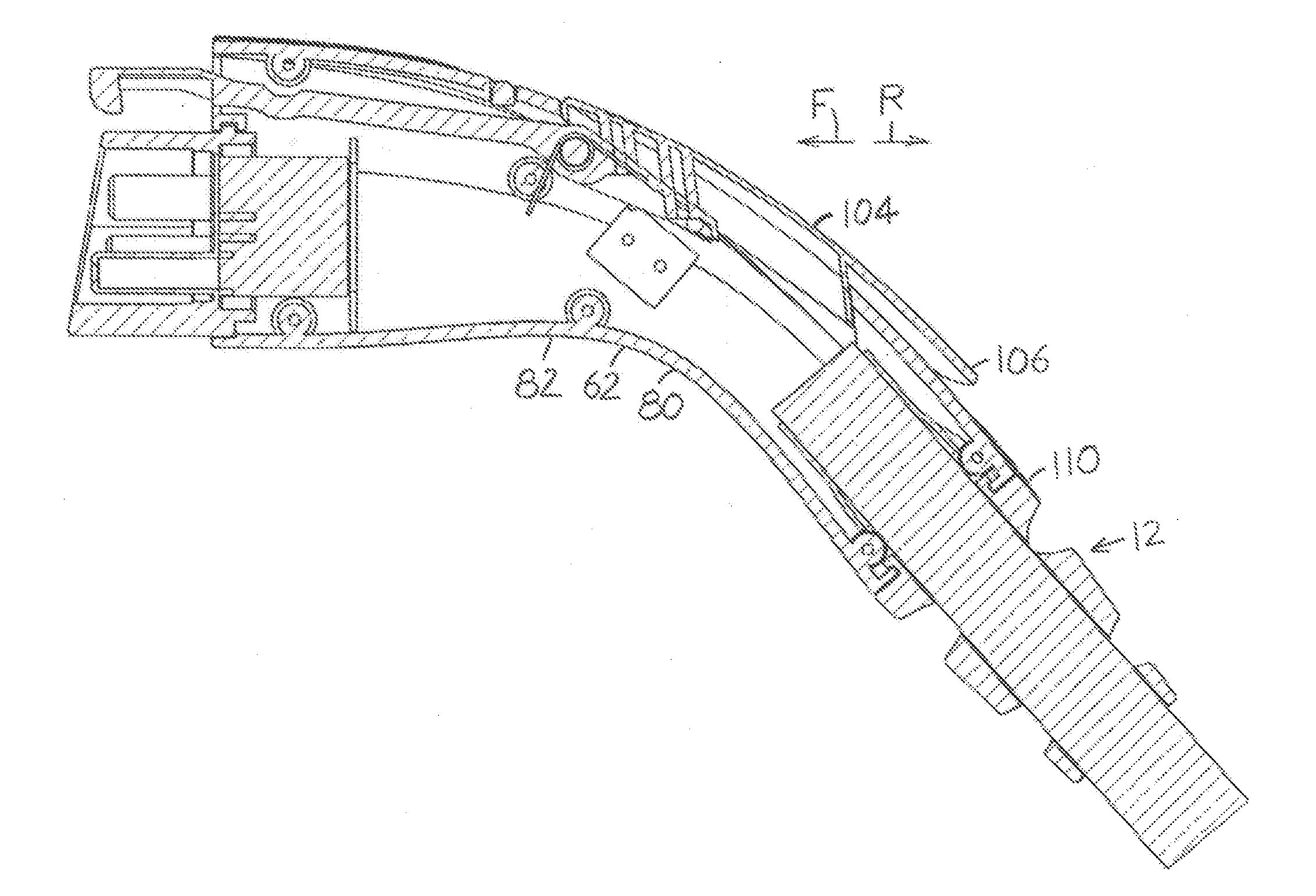
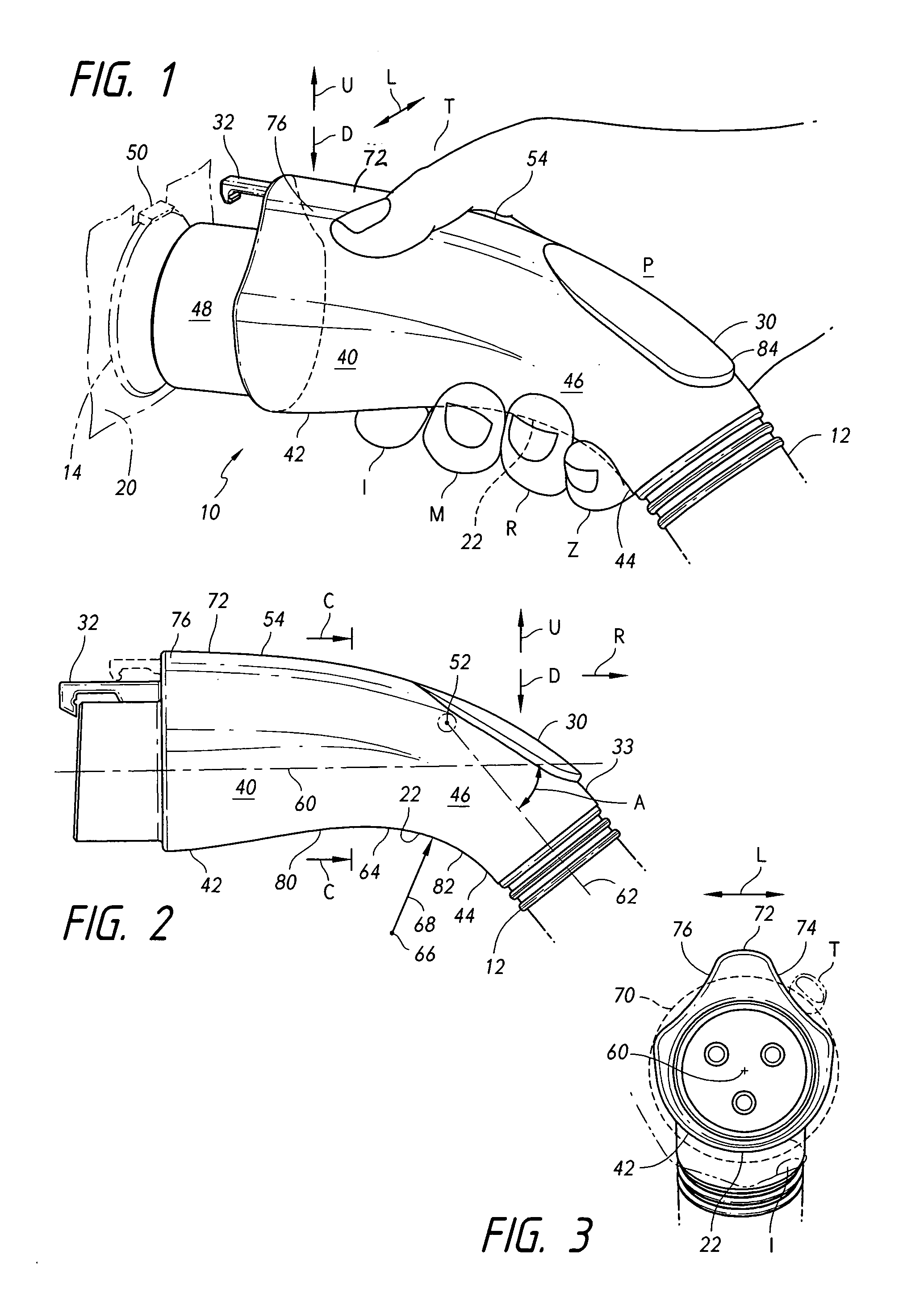
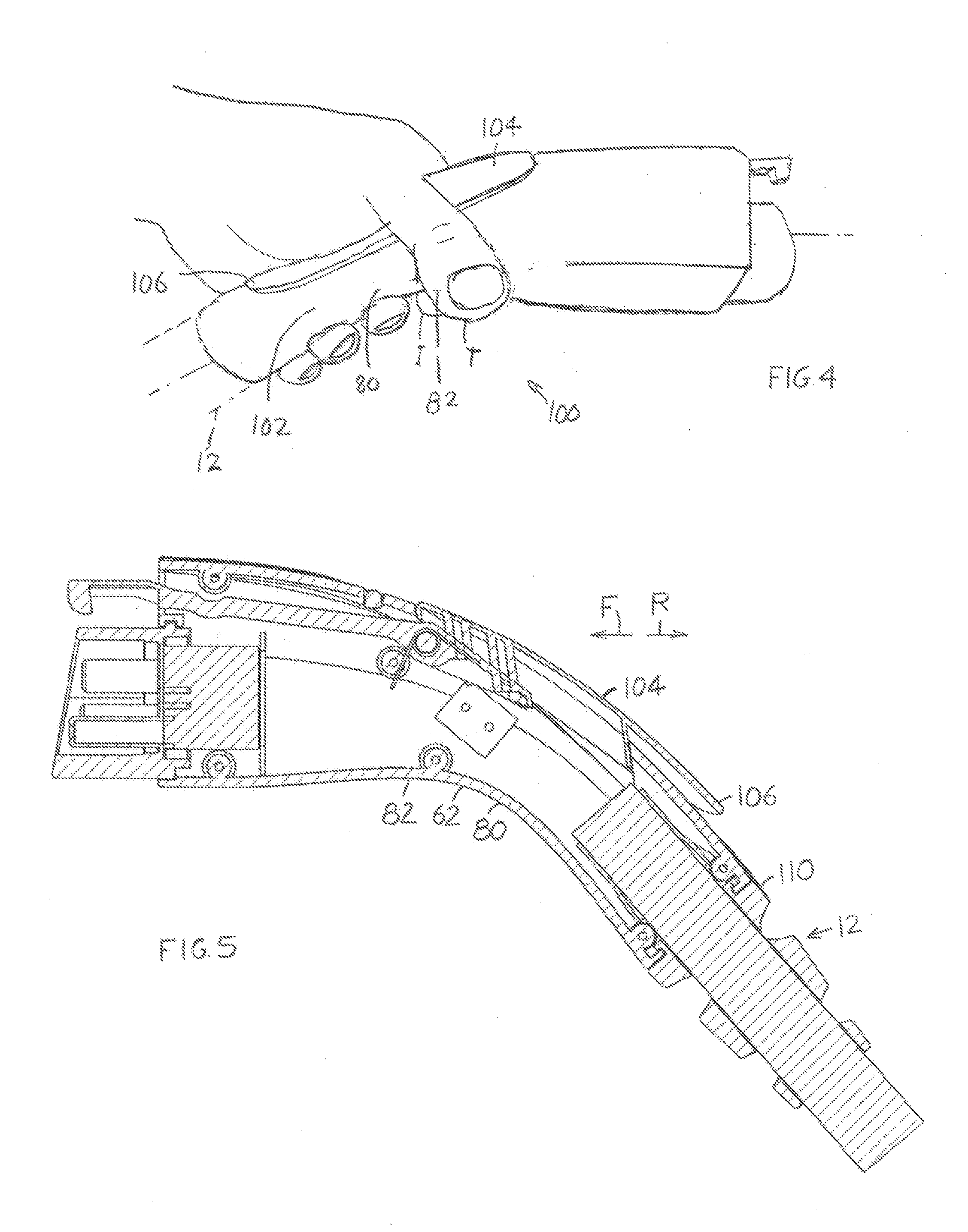
[0016]FIG. 1 shows an electrical connector 10 which lies at the end of a cable 12 and which is designed to connect to a mating connector or electrical receiver 14. In most cases, the receiver 14 is mounted on an electrically powered (with or without an auxiliary gas engine) vehicle 20. The system is designed to carry considerable current to rapidly charge vehicle electrical cells, or batteries, and the connector may have a weight of a plurality of pounds. The connector is designed to be held and connected in a way that is obvious from the shape of the connector and that automatically latches and unlatches the connector. That is, a person grasps the connector with his thumb T extending partially around the top and with his other fingers (non thumb fingers comprising the index I, middle M, ring R and little Z fingers) extending partially around the bottom 22 of the connector. Furthermore, a palm pad 30 is automatically depressed by the person's palm P to operate a latch 32 when the pe...


PUM


Abstract

An electrical connector (10) which facilitates its proper holding for insertion and latching to a charging station receiver (14). The connector has a body (40) with a front portion (42) that extends along a horizontal axis (60), a rear portion (44) that extends at a rearward-downward inclined axis (62) of approximately 45°, and a middle portion (46) with a bottom (22) that is concavely curved to receive the small fingers of a hand. The front portion of the body has grooves (76) on opposite sides of a top ridge (72), so the person's thumb fits around the ridge and into a groove. A palm pad (30) lies immediately rearward of the top ridge and is automatically depressed by the person's palm to operate a latch (32).

Description

BACKGROUND OF THE INVENTION[0001]There are plans to establish a large number of charging stations to charge electrically powered vehicles. At each station, a person would insert an electrical connector (e.g. lying at the end of a cable connected to the station) into an electrical receiver on the vehicle and latch it in place. The electrical connector carries high current and may have a weight of a plurality of pounds, so it is desirable to provide a connector that encourages handling in a natural and obvious way.[0002]Prior connectors of this type have latches controlled by triggers operated by the thumb or index finger. Many people are confused as to how to operate them.SUMMARY OF THE INVENTION[0003]In accordance with one embodiment of the present invention, an electrical connector is provided for grasping in the hand, and for insertion into an electrical receiver, that establishes an electrical connection and a substantially automatic latching to the receiver. The connector includ...

Claims


Application Information

Patent Timeline
Patent Type & Authority Applications(United States)
IPC IPC(8): H01R13/627H01R13/46
CPCB60L11/1818B60L2230/12H01R13/6275B60L2270/34Y02T10/7005Y02T90/121Y02T90/14Y02T10/7088B60L53/16B60L53/18Y02T10/7072Y02T10/70Y02T90/12
Inventor TEICHMANN, KEITH
Owner ITT MFG ENTERPRISES LLC
Why Eureka
Try Eureka