Self-Optimizing Odorant Injection System

a technology of odorant injection and self-optimization, which is applied in the direction of service pipe system, multiple way valve, process and machine control, etc., can solve the problems of dangerous dead time between doses, by-pass style system failure to accurately measure and control the amount of odorant being added to the stream, etc., to achieve safe perception levels, high volume odorization, and accurate measurement and control of the amount of odoran

Active Publication Date: 2012-07-05
LINC ENERGY SYST
View PDF2 Cites 5 Cited by
  • Summary
  • Abstract
  • Description
  • Claims
  • Application Information

AI Technical Summary

Benefits of technology

[0015]The present invention solves many of the previously encountered problems of dead time and / or accuracy in high volume systems of the type under consideration. The method and apparatus of the invention provide the safest method presently available to accurately odorize mid to large gas streams. In addition, as will be apparent from the written description which follows, the system of the present invention also has the added benefit of providing a means for small odorizers, such as the Z9000.™ unit referenced in the following Detailed Description Of The Invention, to odorize small streams without requiring the storage tank to be maintained above pipeline pressure.
[0018]In yet another aspect of the invention, an electronic controller controls a linear thruster. This option has the ability to deliver small to large volume / stroke by precisely controlling the displacement rod of the linear thruster and measuring the force. This arrangement eliminates the need for a separate metering unit. In addition to monitoring the forces of the linear thruster, an optional pressure transmitter monitors the hydraulic and / or odorant pressures of the system. This information is fed directly to the primary controller to verify and / or augment the data from the linear thruster.

Problems solved by technology

These methods can leave dangerous dead time between doses.
By-pass style systems fail to accurately measure and control the amount of odorant being added to the stream.

Method used


Image

  • Self-Optimizing Odorant Injection System
  • Self-Optimizing Odorant Injection System
  • Self-Optimizing Odorant Injection System

Examples


Embodiment Construction

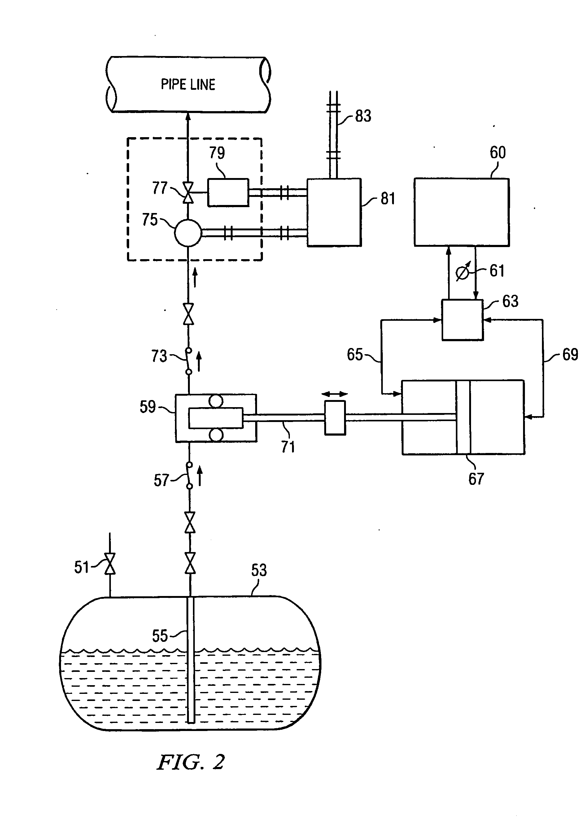
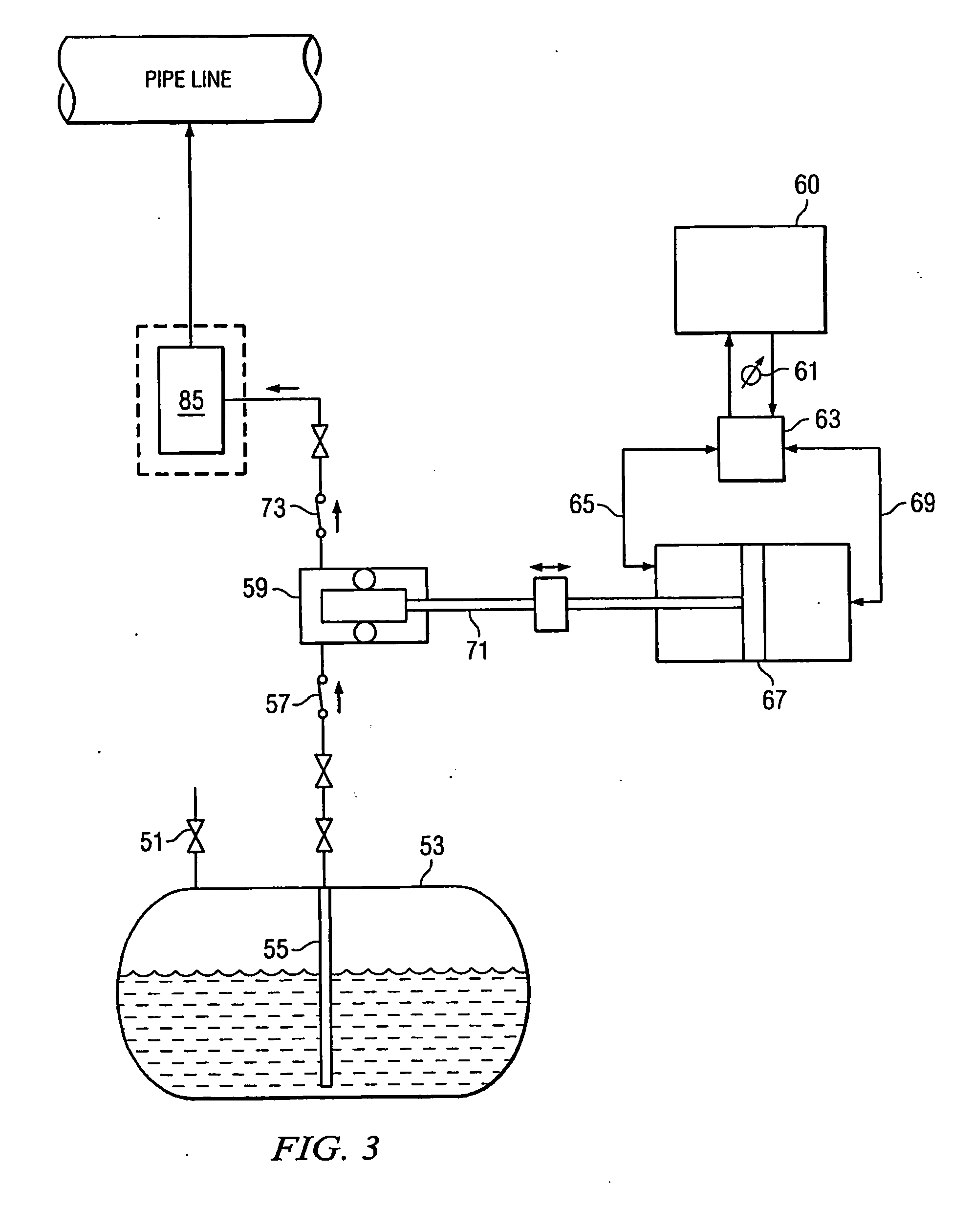
[0029]The present invention has as its object to provide a system for injecting chemicals into a pipeline, such as for injecting an odorant of the type used for odorizing natural gas, which is simpler in design and more economical in operation than the prior art systems, which is more reliable, and which can be used in both small and large flow applications as well as to inject chemicals into liquefied petroleum gas (LPG) pipelines.

[0030]The present invention offers several unique advantages over existing chemical injection and odorization systems in both small and larger flow rate applications. It has particular applicability to odorization systems for natural gas pipelines and LPG pipelines but those skilled in the art will understand that the system can also be used to inject other chemical substances, such as alcohol to inhibit freezing, corrosion inhibitors, and the like.

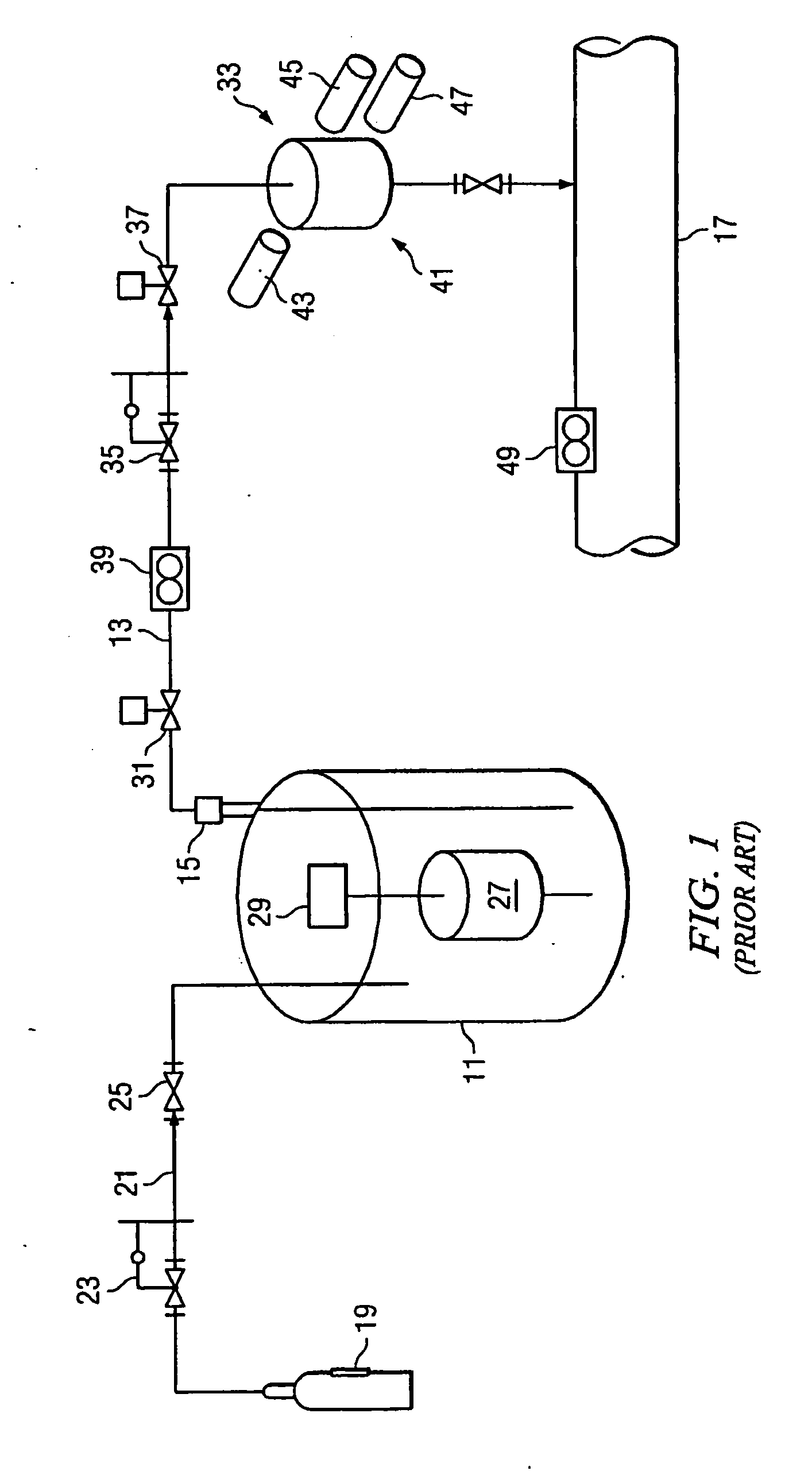
[0031]A number of problems inherent in the prior art systems are overcome with the odorization system of the...


PUM

PropertyMeasurementUnit
pressureaaaaaaaaaa
pressureaaaaaaaaaa
pressureaaaaaaaaaa

Abstract

A method for injecting a chemical, such as an odorant, from a chemical supply into a fluid-containing system such as a natural gas or an LPG pipeline. A tank of odorant is maintained at a pressure above ambient, but below pipeline pressure. An injection conduit communicates the odorant tank with the pipeline. A hydraulic pressure booster is located in the injection conduit for pressurizing the chemical to a pressure above that of the pipeline. Flow-control apparatus located within the injection conduit for metering chemical to be injected into the pipeline is either (a) drip-style metering valve adjustable between a drop-wise setting and a steady-flow setting or (b) a pair of valves one of which is a flow valve allowing larger volumes to be injected and the other which is a drop-wise flow valve for metering smaller volumes of the chemical.

Description

RELATED APPLICATIONS[0001]The present application claims priority from U.S. patent application Ser. No. 12 / 407,387, filed Mar. 19, 2009, which claims priority from Provisional Patent Application Ser. No. 61 / 039,606, filed Mar. 26, 2008, and Provisional Patent Application Ser. No. 61 / 039,610, filed Mar. 26, 2008.FIELD OF INVENTION[0002]The present invention relates generally to apparatus and methods for injecting chemicals into pipelines and, more specifically, to apparatus and methods for adding odorant to natural gas or liquefied petroleum gas flowing in a pipeline.DESCRIPTION OF THE PRIOR ART[0003]There are many instances in which it is desirable to inject chemicals of various types into fluids (gas and liquids) flowing in pipelines. One such example is in the area of natural gas pipelines. In addition to substances such as corrosion inhibitors and alcohol to inhibit freezing, odorants are commonly injected into natural gas pipelines. Natural gas is odorless. Odorant is injected i...

Claims


Application Information

Patent Timeline
Patent Type & Authority Applications(United States)
IPC IPC(8): C10J1/28
CPCG05D11/132F17D3/12Y10T137/0363Y10T137/2531Y10T137/87684Y10T137/8158Y10T137/87676Y10T137/2514Y10T137/2529Y10T137/0329Y10T137/87692
Inventor ZECK, MARK
Owner LINC ENERGY SYST
Why Eureka
Try Eureka