Supercharge Your Innovation With Domain-Expert AI Agents!

Bicycle Frame With Passive Seat Tube Pivot Joint

a bicycle frame and seat tube technology, applied in the field of bicycle frames, can solve the problems of increasing the weight attributable to the bicycle frame, affecting the performance of the rider, and not particularly suited to extended rides over paved terrain

Active Publication Date: 2012-07-05
TREK BICYCLE CORPORATION
View PDF0 Cites 26 Cited by
  • Summary
  • Abstract
  • Description
  • Claims
  • Application Information

AI Technical Summary

Benefits of technology

[0010]Another aspect of the invention that is useable with one or more of the above aspects discloses a bicycle frame assembly that includes a forward frame triangle that includes a top tube and a bottom tube. The top tube includes a first end that is connected to a head tube and a second end. The bottom tube includes a first end that is connected to the head tube and a second end. A bottom bracket is connected to the second end of the bottom tube. A seat tube extends in an upward direction from the bottom bracket and a pair of seat stays is connected to the top tube and extends in a rearward direction beyond the forward frame triangle. A pivot connects the seat tube to the forward frame triangle proximate the top tube at a location nearer a bicycle seat than the bottom bracket. The pivot allows that portion of the seat tube disposed between the pivot and the bottom bracket to deflect from an at rest position during vertical loading of the seat tube.

Problems solved by technology

However, such robust suspension systems do not particularly lend themselves to extended rides over paved terrain.
The robust nature of such systems increases the weight attributable to the bicycle assembly.
During rides intended to test rider stamina, endurance, and conditioning, such robust suspension systems would detrimentally affect rider time performance.
However, even paved surfaces can present discontinuities wherein most riders would prefer some degree of bicycle suspension to limit or reduce the forces communicated to the rider from payment discontinuities.
In achieving the desired vertical compliance, the bicycle frame of U.S. Pat. No. 6,932,371 includes a number of supplemental structures that, in improving vertical compliance, detrimentally affect the overall weight of the underlying bicycle assembly.

Method used


Image

  • Bicycle Frame With Passive Seat Tube Pivot Joint
  • Bicycle Frame With Passive Seat Tube Pivot Joint
  • Bicycle Frame With Passive Seat Tube Pivot Joint

Examples


Embodiment Construction

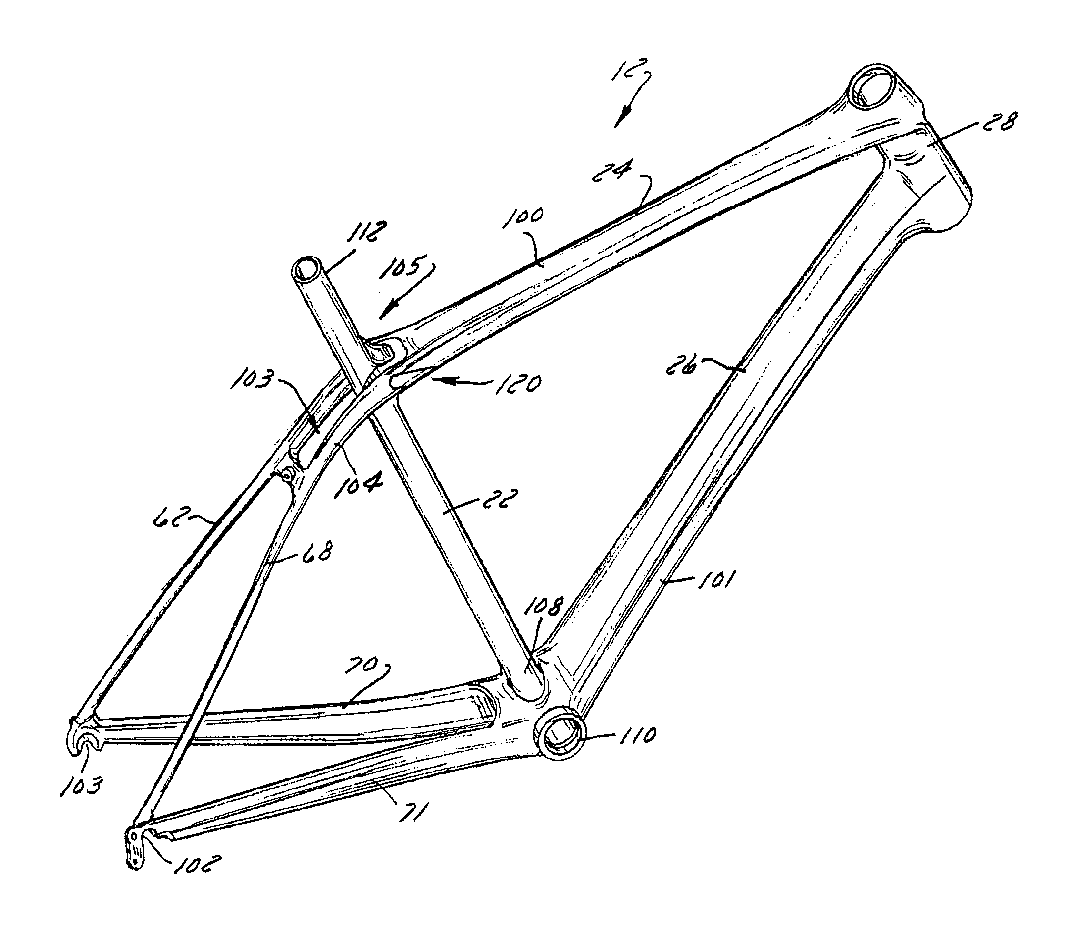
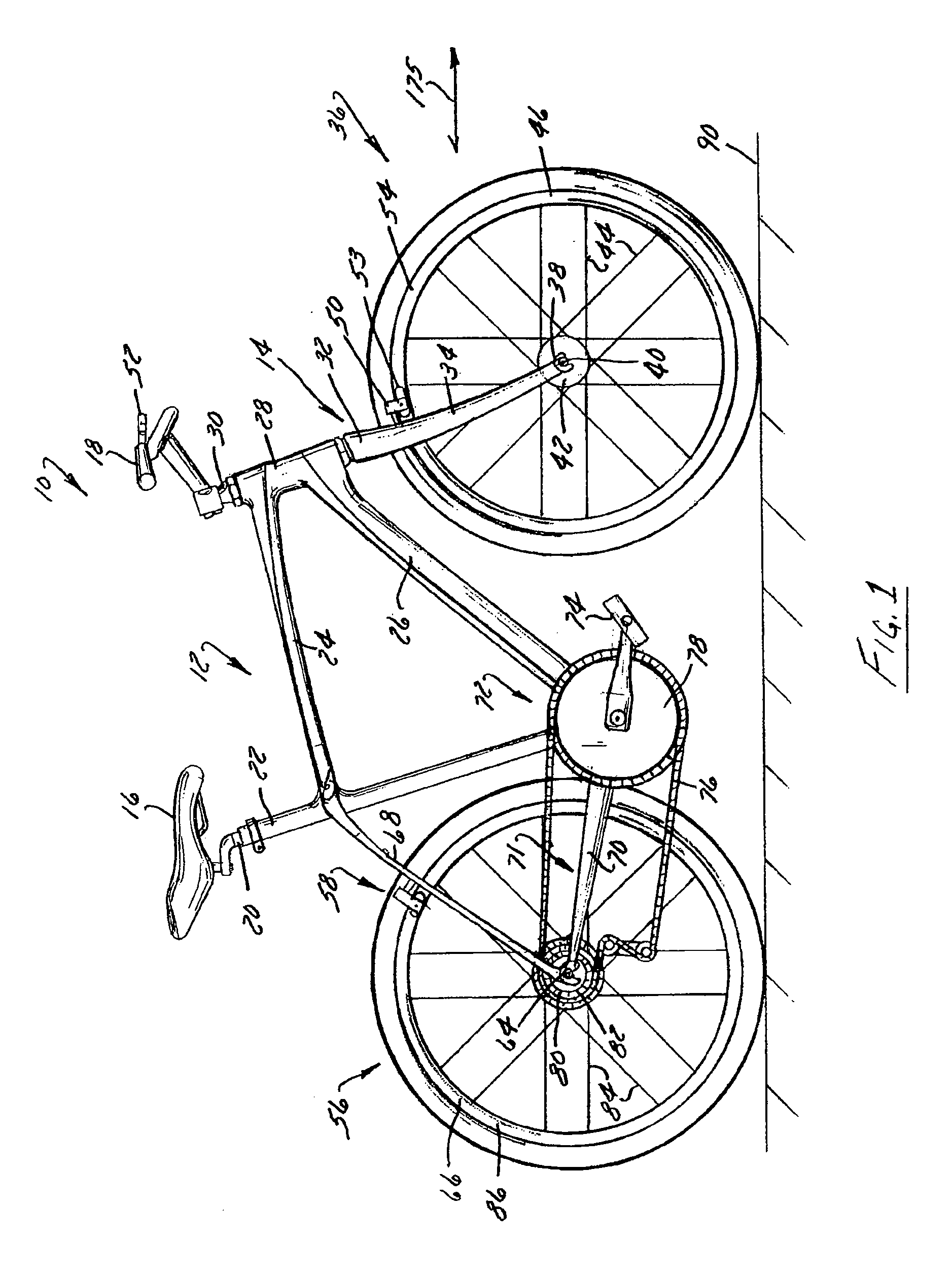
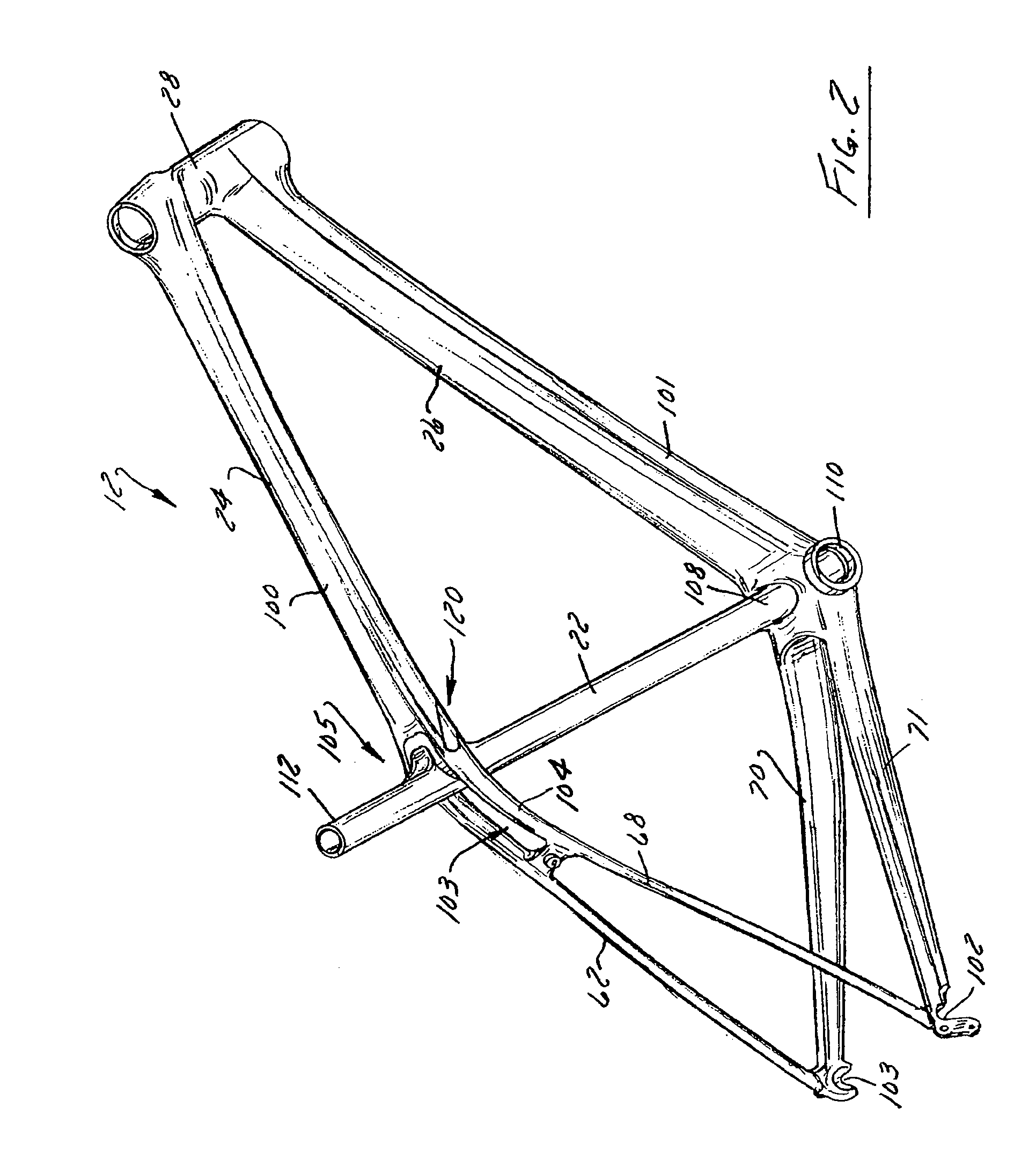
[0021]FIG. 1 shows a bicycle 10 having a frame assembly 12 according to the present invention. Bicycle 10 includes a seat 16 and handlebars 18 that are attached to frame assembly 12. A seat post 20 is connected to seat 16 and slidably engages a seat tube 22 of frame assembly 12. A top tube 24 and a down tube 26 extend forwardly from seat tube 22 to a head tube 28 of frame 12. Handlebars 18 are connected to a stem or steer tube 30 that passes through head tube 28 and is connected or integrally formed with a fork crown 32. Understandably, handlebar 18 may include a stem that is constructed to slidably engage an interior cavity of steer tube 30. It is appreciated that one or more of the structures of bicycle 10 and frame assembly 12 can be constructed from similar materials, a variety of different materials, and various combinations thereof. Preferably, frame assembly 12 and seat tube 22 are formed of metal-type materials, such as aluminum-type materials, carbon fiber materials, and / or...


PUM

PropertyMeasurementUnit
Angleaaaaaaaaaa

Abstract

A bicycle frame assembly that includes an upper frame member and a lower frame member that each extend between a head tube and a dropout. A seat tube extends between the upper frame member and the lower frame member. The seat tube is preferably connected to a bottom bracket of the lower frame member and is connected by a pivot to the upper frame member so that the seat tube can deflect from a rest position without altering an orientation of a top tube to a bottom tube of the upper and lower frame members, respectively.

Description

CROSS-REFERENCE TO RELATED APPLICATIONS[0001]The present invention claims priority to U.S. Provisional Patent Application Ser. No. 61 / 430,011 filed on Jan. 5, 2011 and the disclosure of which is expressly incorporated herein.BACKGROUND OF THE INVENTION[0002]The present invention relates to bicycles and, more particularly, to a bicycle frame assembly wherein the seat tube is connected at an overlapping intersection of a top tube and the seat stays by a passive pivot that allows the seat stay to deflect from a generally linear at-rest orientation to improve the vertical compliance of the bicycle frame.[0003]The primary structural component of a conventional two-wheel bicycle is the frame. On a conventional road bicycle, the frame is typically constructed from a set of tubular members assembled together to form the frame. For many bicycles, the frame is constructed from members commonly referred to as the top tube, down tube, seat tube, seat stays and chain stays, and those members are...

Claims


Application Information

Patent Timeline
IPC IPC(8): B62K3/02B23P11/00
CPCB62K19/18B62K19/36Y10T29/4984B62K2025/041B62K25/04B62J1/04B62K3/02B62K19/16
Inventor LUND, REGGIEPOMERING, CHRISTOPHER
Owner TREK BICYCLE CORPORATION
Features
  • R&D
  • Intellectual Property
  • Life Sciences
  • Materials
  • Tech Scout
  • Unparalleled Data Quality
  • Higher Quality Content
  • 60% Fewer Hallucinations
Learn More