Linear vibration motor

a linear vibration and motor technology, applied in the direction of electrical apparatus, dynamo-electric machines, etc., can solve the problem of limited thickness of the linear vibration motor designed to be vibrated in a vertical direction, and achieve the effect of increasing the collection of magnetic for

Inactive Publication Date: 2012-07-05
MPLUS
View PDF8 Cites 104 Cited by
  • Summary
  • Abstract
  • Description
  • Claims
  • Application Information

AI Technical Summary

Benefits of technology

[0030]The fixing part may be coupled with a plate yoke coupled between

Problems solved by technology

However, the linear vibration motor designed to be vibrated in a vertical direction has a limitation in thickness in that it is not linearly vibrat

Method used


Image

  • Linear vibration motor
  • Linear vibration motor
  • Linear vibration motor

Examples


first preferred embodiment

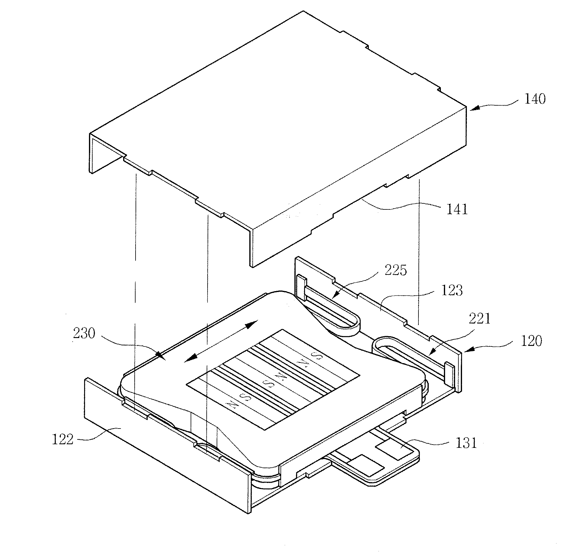
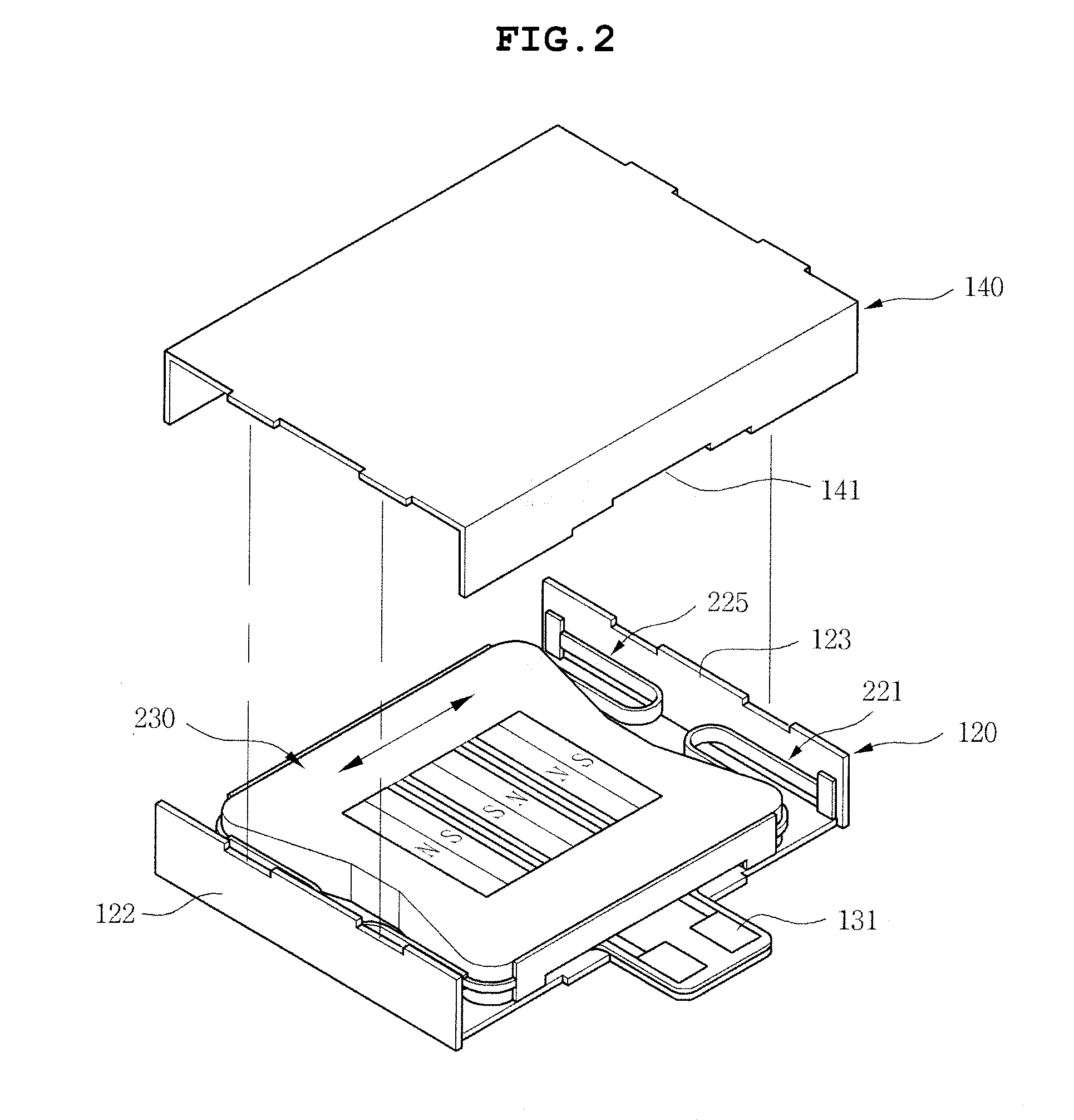
[0043]FIG. 2 is a coupling perspective view of a vibrator according to a first preferred embodiment of the present invention. As shown in FIG. 2, the linear vibration motor may be configured to include a fixing part 100 and a vibrator part 200.

[0044]The fixing part 100 may be configured to include a coil 110, a bracket 120, a printed circuit board 130, and a case 140 and the vibrator part 200 may be configured to include a plurality of magnets 211, 212, and 213, a plurality of elastic members 221 and 225, a weight body 230, and a plate yoke 240.

[0045]FIG. 3 is a perspective view of a vibrator part configuring a linear vibration motor shown in FIG. 2 and FIG. 4 is a perspective view of a fixing part configuring a linear vibration motor shown in FIG. 2.

[0046]In detail, the coil 110 is coupled with the upper portion of the printed circuit board 130.

[0047]The printed circuit board 130 is provided with circuit patterns (not shown) in order to apply external power to the coil 110 and incl...

second preferred embodiment

[0075]FIG. 6 is a perspective view of a linear vibration motor according to a second preferred embodiment of the present invention, FIG. 7 is a perspective view of a vibrator part configuring the linear vibration motor shown in FIG. 6, FIG. 8 is a perspective view of a fixing part configuring the linear vibration motor shown in FIG. 6, and FIG. 9 is an exploded perspective view of the linear vibration motor according to the second preferred embodiment of the present invention.

[0076]The technical features of the linear vibration motor according to a second preferred embodiment of the present invention is the same as the first preferred embodiment of the present invention and therefore, the technical features thereof will be omitted.

[0077]As shown, the linear vibration motor may be configured to include a fixing part 300 and a vibrator part 400.

[0078]The fixing part 300 may be configured to include a plurality of magnets 311, 312, and 313, a bracket 320, a plate yoke 330, a case 340, ...


PUM


Abstract

Disclosed herein is a linear vibration motor, including: a fixing part, a vibrator part vibrating in a horizontal direction, and an elastic member coupled with the outer side of the vibrator part and a round-shaped bending part to elastically support the fixing part opposite to the vibrator part linearly vibrating in a horizontal direction.

Description

CROSS REFERENCE TO RELATED APPLICATION[0001]This application claims the benefit of Korean Patent Application No. 10-2010-0139974, filed on Dec. 31, 2010, entitled “Linear Vibration Motor” which is hereby incorporated by reference in its entirety into this application.BACKGROUND OF THE INVENTION[0002]1. Technical Field[0003]The present invention relates to a linear vibration motor.[0004]2. Description of the Related Art[0005]A general vibration motor, which is a component that uses a principle of generating electromagnetic force and converts electrical energy into mechanical vibrations, is mounted in mobile communication terminals, portable terminals, or the like, to silently notify a call to a user.[0006]Recently, a linear vibration motor has been generally used as a vibration motor. The linear vibration motor is generally disposed at a corner portion of a device to generate vibrations in a direction vertical to an object receiving vibrations.[0007]As shown in FIG. 1, the linear vib...

Claims


Application Information

Patent Timeline
IPC IPC(8): H02K35/02
CPCH02K33/18H02K33/16
Inventor KIM, YONG JINLEE, KYUNG HOCHOI, JUN KUNOH, HWA YOUNG
Owner MPLUS
Why Eureka
Try Eureka