Separation Device

Inactive Publication Date: 2012-07-12
VIPER INNOVATIONS LTD
View PDF7 Cites 11 Cited by
  • Summary
  • Abstract
  • Description
  • Claims
  • Application Information

AI Technical Summary

Benefits of technology

[0009]According to the invention there is provided a subsea separation device for use in separating a pair of stabplate connector plates, the subsea separation device comprising a first engagement member adapted to engage, in use, a first one of the connector plates, or a component rigidly secured thereto, a second engagement member adapted to engage, in use, a second one of the connector plates or a component rigidly secured thereto, and drive means operable to urge the first and second engagement members apart and so urge the connector plates apart.
[0010]The drive means may comprise, for example, at least one hydraulic ram, in practise several such rams conveniently being used, operable to urge apart the engagement members. Alternatively, an electrically powered motor may be used, for example to drive a screw ac

Problems solved by technology

Furthermore, where chemical lines or hydraulic lines are provided, the valves incorporated into the connectors thereof may result in separation of the connector plates drawing a vacuum, and so a relatively large separating load may be required to force the connector plates apart against the drawing of such a vacuum.
There may be circumstances in which the separating load applied by such a securing mechanism is insufficient or cannot be used to achieve separation.
For example, the separating load may be insufficient to break apart the marine deposits.
Furthermore, there may be circumstances in which a seconda

Method used


Image

  • Separation Device
  • Separation Device
  • Separation Device

Examples


Example

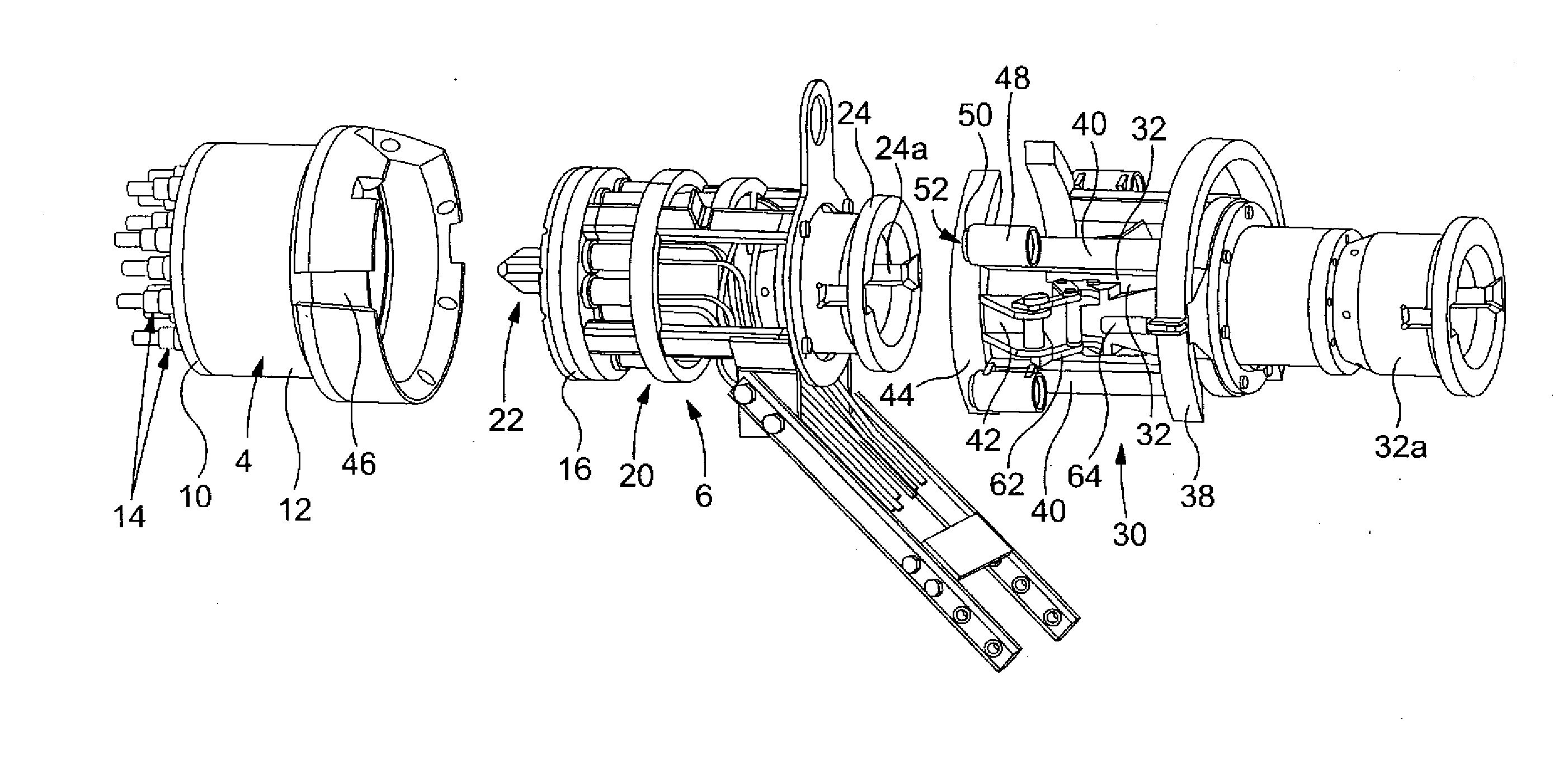
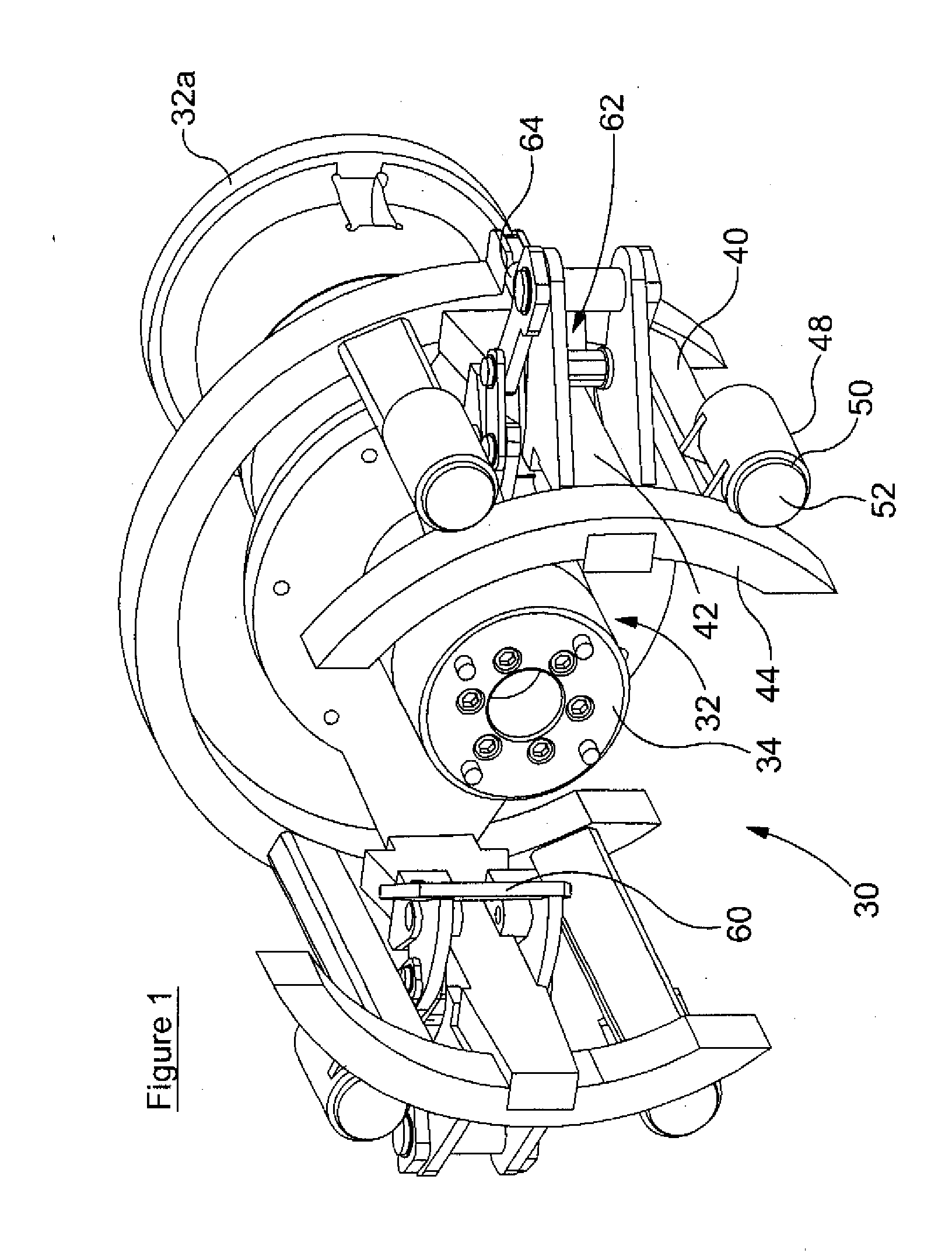
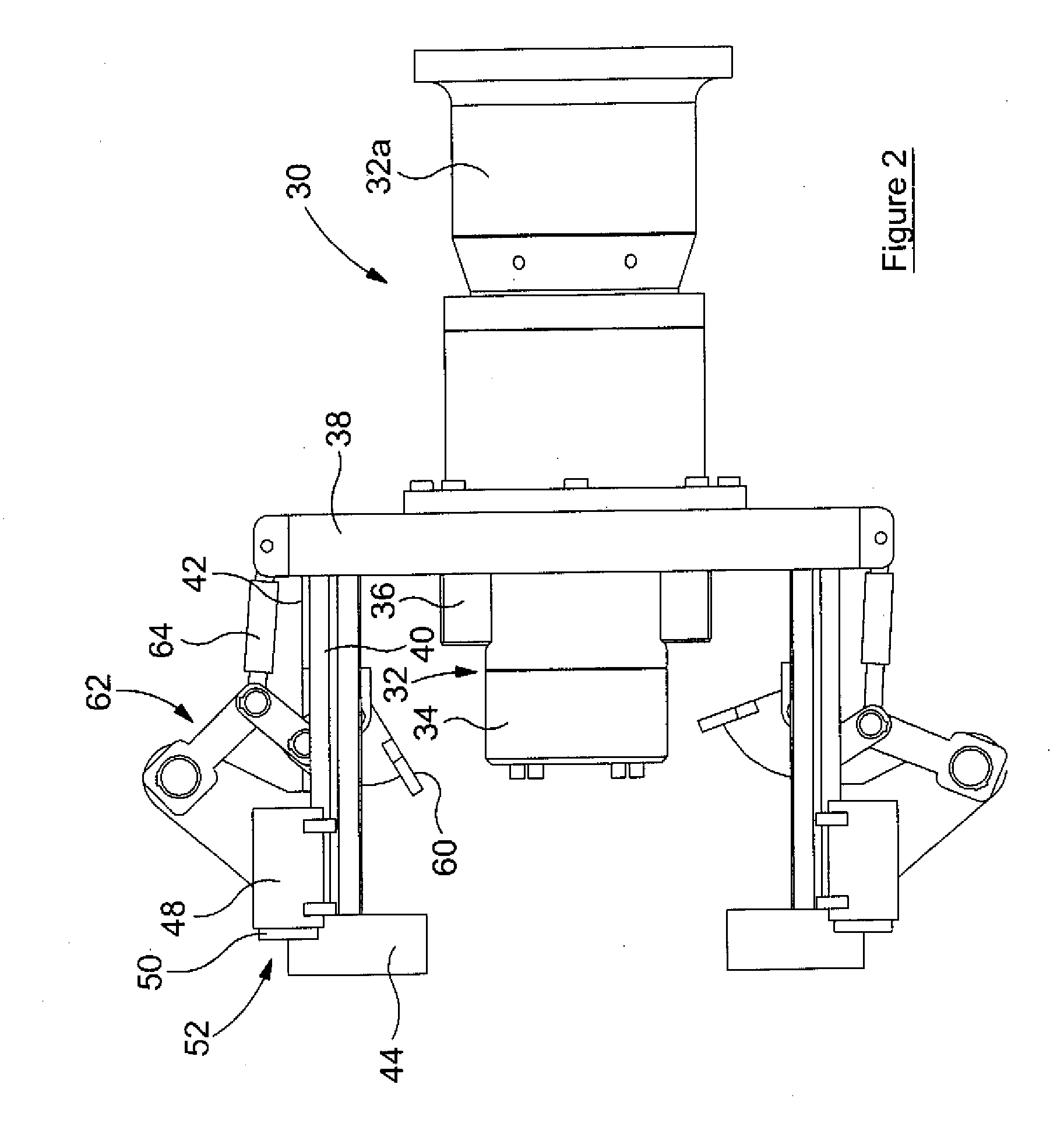
[0018]Referring to the accompanying drawings, a stabplate of the general form described and illustrated in greater detail in GB2467192 is shown. The stabplate comprises a first, fixed stabplate part 4 to which a second, flying stabplate part 6 can be secured. The first stabplate part 4 comprises a fixed connector plate 10 secured to a tubular socket housing 12 which in turn is secured, in use, to a housing (not shown) of a piece of subsea equipment. The connector plate 10 includes a series of individual connectors 14 which are connected, via associated lines, to parts of the equipment to supply power thereto and / or carry control signals between parts of the equipment and a remote location. Some of the connectors 14 may take the form of electrical connectors. Others may provide hydraulic connections or permit the supply of chemicals to the equipment. These connectors are conveniently provided with poppet valves or the like to prevent or restrict the escape of fluid or ingress of sea ...


PUM


Abstract

A subsea separation device for use in separating a pair of stabplate connector plates, the subsea separation device comprising a first engagement member adapted to engage, in use, a first one of the connector plates, or a component rigidly secured thereto, a second engagement member adapted to engage, in use, a second one of the connector plates or a component rigidly secured thereto, and drive means operable to urge the first and second engagement members apart and so urge the connector plates apart.

Description

BACKGROUND OF THE INVENTION[0001]This invention relates to a separation device and in particular to a separation device suitable for use in subsea locations to permit the separation of stabplates once the retainer or retaining mechanism used to secure the stabplates to one another, in use. has been disengaged.[0002]The use of equipment located at the sea bed is commonplace in the extraction of oil and gas from subsea wells, for example to control the pumping of hydrocarbon materials therefrom. Although the majority of the description herein relates to use in relation to the extraction of hydrocarbon materials, it will be appreciated that the invention is not restricted in this regard, and may be used in, for example, off-shore electrical generation and other subsea applications. Typically, a number of individual pieces of equipment are connected to a distribution unit via a series of flying leads. The distribution unit is connected to remotely located equipment, for example at the s...

Claims


Application Information

Patent Timeline
IPC IPC(8): E21B17/02
CPCE21B33/0355E21B33/038H02G9/02E21B41/04E21B41/0007B63C11/52E21B43/01
Inventor ROBERTS, PAULDUNKERTON, THOMAS
Owner VIPER INNOVATIONS LTD
Why Eureka
Try Eureka