Bearing having a power generation unit

Inactive Publication Date: 2012-07-12
SCHAEFFLER TECH AG & CO KG
View PDF3 Cites 4 Cited by
  • Summary
  • Abstract
  • Description
  • Claims
  • Application Information

AI Technical Summary

Benefits of technology

[0012]Provision is made for the induction coil and the magnetic poles to be combined to form a common structural unit, which is fastened on the second bearing ring. In this case, the induction coil is received in an electrically insulated receptacle consisting of plastic, for example. The magnetic poles can likewise be received in the plastic and can be arranged at a rim of the plastic so as to form the magnetically conductive connection to the second bearing ring, with the result that, when the structural unit is fitted, the magnets make direct magnetically conductive contact with a lateral surface of the second hearing ring. In the process, the plastic keeps the magnetic poles physically separated and magnetically isolated from one another.
[0013]Provision is made for the claw ring to have a body in the form of a circular ring with a radial slit. The radial slit in the claw ring suppresses eddy currents between adjacent claws in the circumferential direction of the claw ring and increases the effectiveness of the magnetic flux guidance th

Problems solved by technology

A second claw ring is thus superfluous, with the result that additional installation space is available in the axial direction, i.e. along an axis of rotation of the roller bearing, or in the radial direction, i.e. perpendicular to the a

Method used


Image

  • Bearing having a power generation unit
  • Bearing having a power generation unit
  • Bearing having a power generation unit

Examples


Embodiment Construction

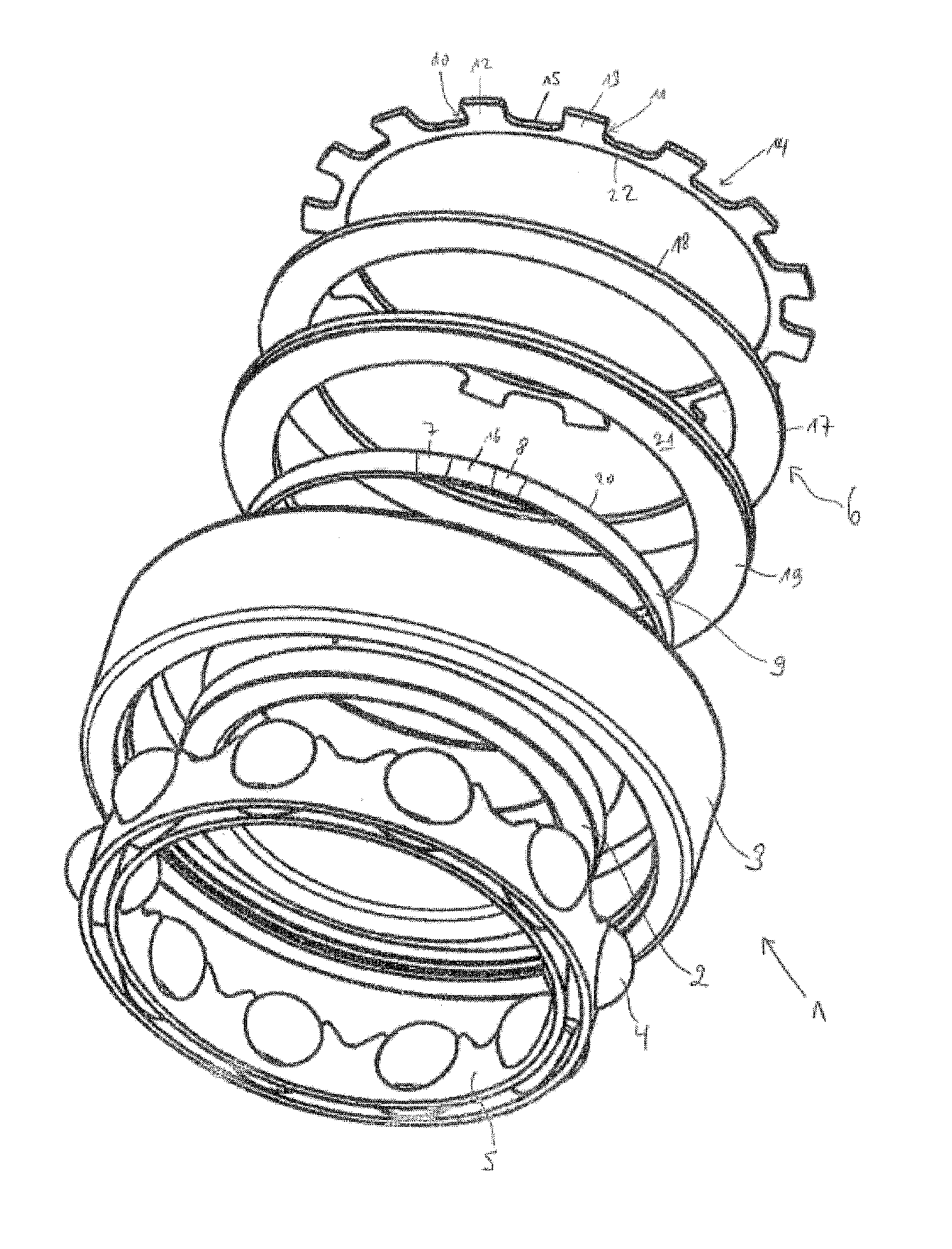
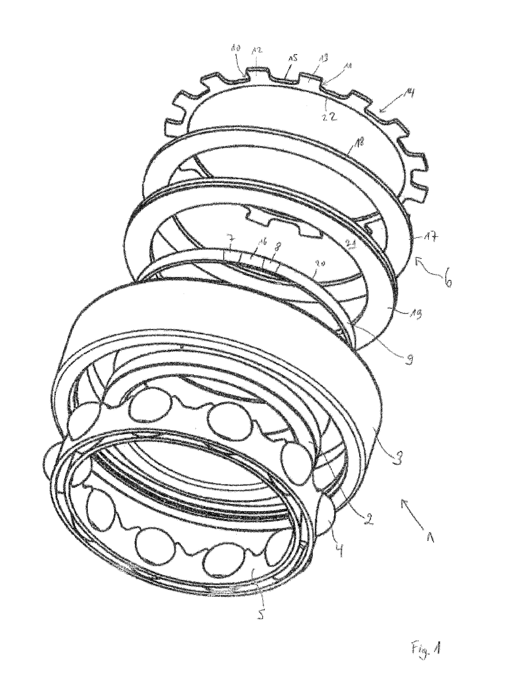
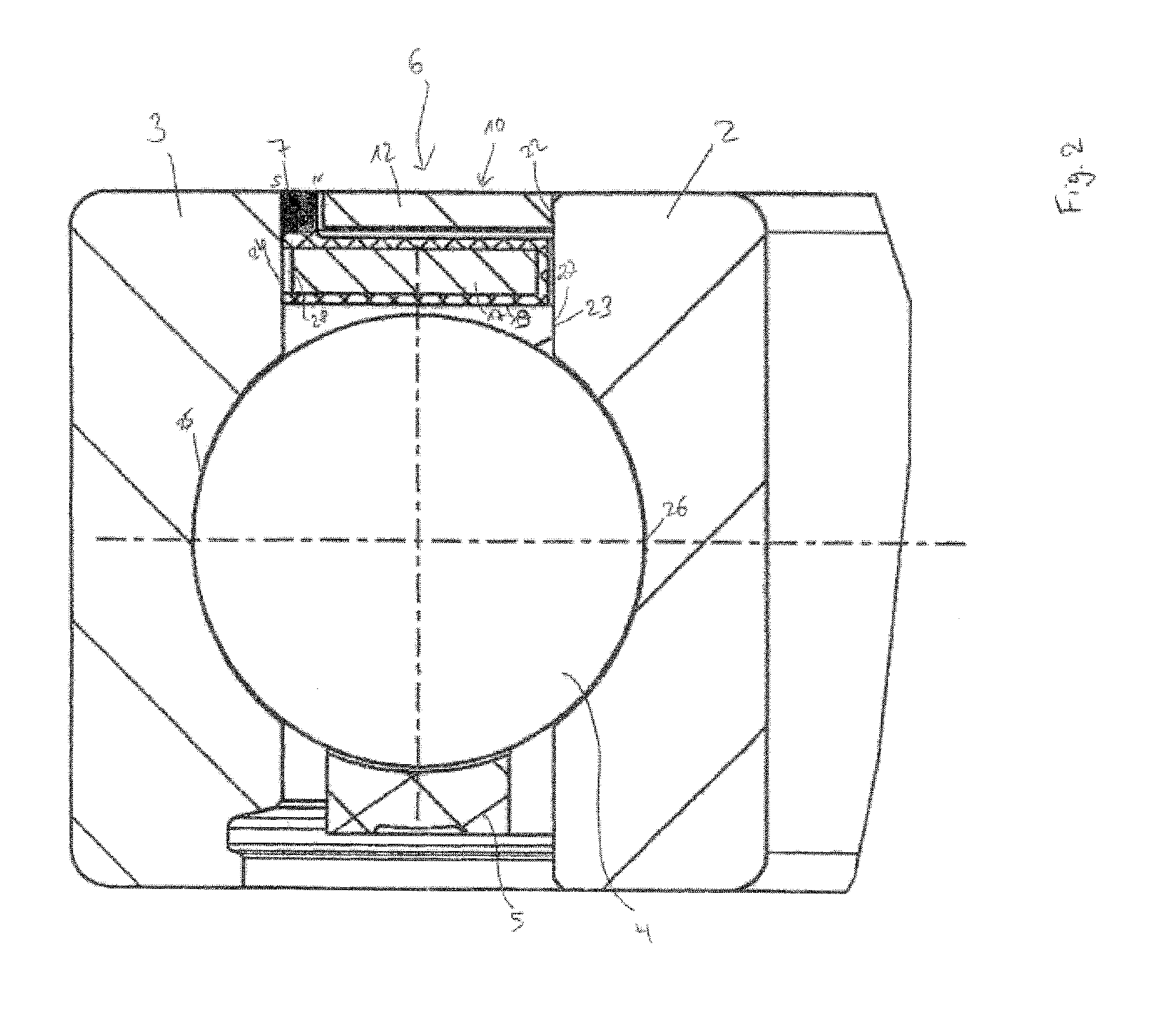
[0019]FIG. 1 shows a hearing 1 in the form of a roller bearing, which comprises a first bearing ring 2 in the form of an inner ring of the bearing 1 and a second bearing ring 3 in the form of an outer ring of the bearing 1. The first bearing ring 2 receives a shaft (riot illustrated in the figure) and hears this shaft rotatably with respect to a hearing receptacle (not illustrated in the figure), on which the second bearing ring 3 is arranged fixedly. The bearing 1 further comprises rolling bodies 4, which are arranged in a cage 5 between the two bearing rings 2, 3 and make it possible for the first bearing ring 2 to rotate relative to the second bearing ring 3.

[0020]The bearing 1 further comprises a power generation unit 6 in the form of a claw pole generator.

[0021]The power generation unit 6 comprises a sequence of magnetic poles running peripherally along a circumference of the second bearing ring 3, with two poles of a first pole pair 7 and a second pole pair 8 being shown., sai...


PUM


Abstract

A bearing, which has a first bearing ring, a second bearing ring, a rolling element interposed between the two bearing rings and a claw pole generator-type power generation unit. The bearing has a substantially space-neutral power generation unit which has a high filling factor for the induction coil. The first claw of the claw ring is connected to a magnetically conducting section of the body of the first bearing ring in a magnetically conducting fashion. The magnetic poles of the pole pairs are mounted so as to be connected to a magnetically conducting section of the body of the second bearing ring in a magnetically conducting fashion and the magnetic circuit is substantially closed via the two magnetic sections and the rolling element.

Description

CROSS-REFERENCE TO RELATED APPLICATIONS[0001]This application is a 371 of PCT / DE2010 / 000773 filed Jul. 1, 2010, which in turn claims the priority of DE 10 2009 031 609.4 filed Jul. 3, 2009. The priority of both applications is hereby claimed and both applications are incorporated by reference herein.BACKGROUND OF THE INVENTION[0002]The invention relates to a bearing, which has a power generation unit.[0003]The prior art discloses bearings which comprise a power generation unit in the form of a claw pole generator. The claw pole generator comprises an induction coil with an electrical conductor which is wound with a plurality of turns. In order to supply a voltage which is sufficient even at low rotation speeds, the induction coil should have a high fill factor, i.e. the electrical conductor should have as high a number of turns as possible.[0004]U.S. Pat. No. 6,838,794 B2 describes a roller bearing, which comprises a first bearing ring, a second bearing ring, a plurality of rolling ...

Claims


Application Information

Patent Timeline
IPC IPC(8): H02K7/08
CPCF16C41/004H02K7/09H02K7/1846F16C19/06H02K7/088H02K7/1807
Inventor RINK, THOMAS
Owner SCHAEFFLER TECH AG & CO KG
Why Eureka
Try Eureka