Magnetic resonance imaging system with thermal reservoir and method for cooling

Active Publication Date: 2012-07-12
GENERAL ELECTRIC CO
View PDF3 Cites 18 Cited by
  • Summary
  • Abstract
  • Description
  • Claims
  • Application Information

AI Technical Summary

Problems solved by technology

The resulting structure is not only expensive to manufacture, but heavy.
Additionally, in some instances the helium vessel may not be completely filled, such as to save cost.
Accordingly, the likelihood of instability a

Method used


Image

  • Magnetic resonance imaging system with thermal reservoir and method for cooling
  • Magnetic resonance imaging system with thermal reservoir and method for cooling
  • Magnetic resonance imaging system with thermal reservoir and method for cooling

Examples


Embodiment Construction

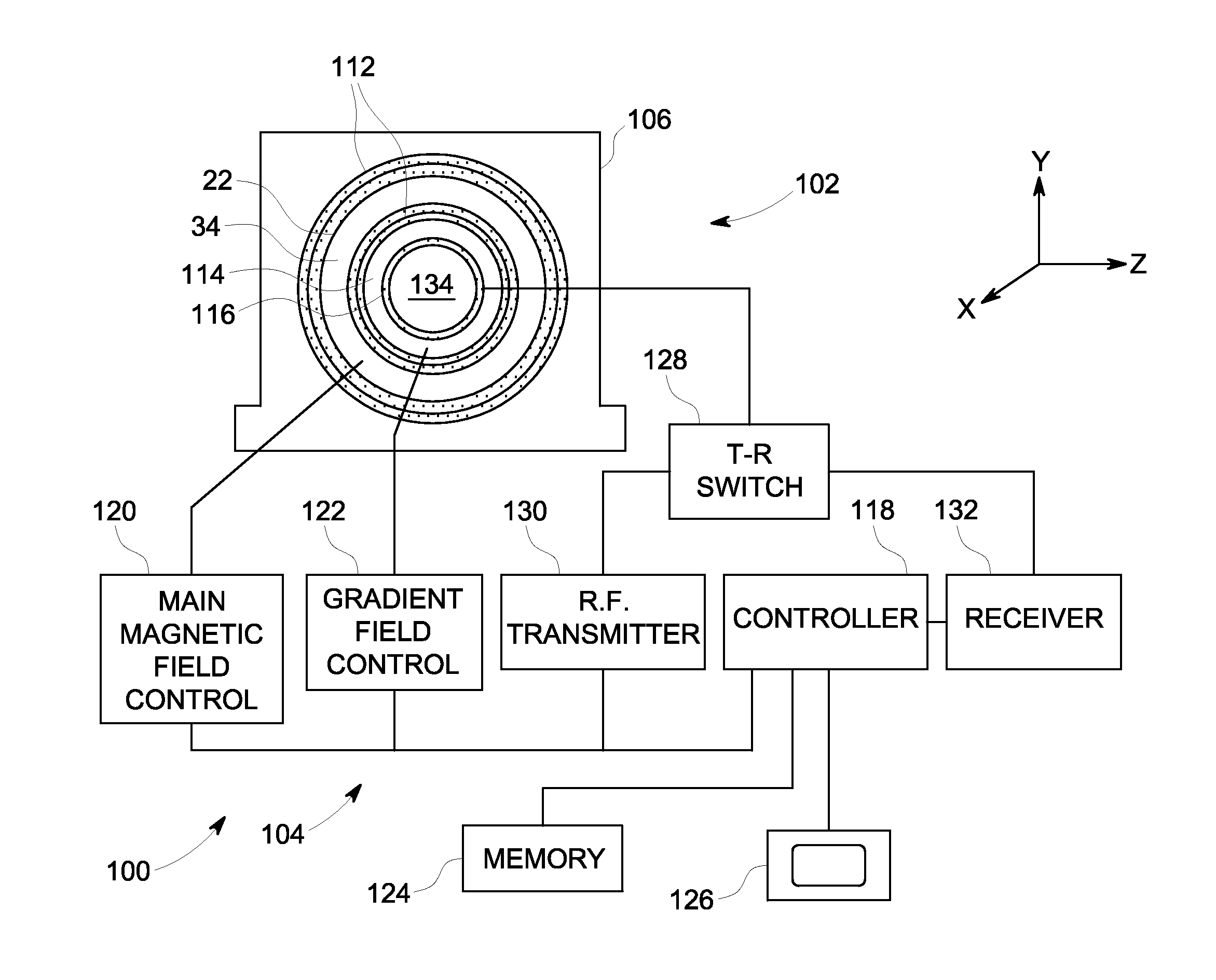
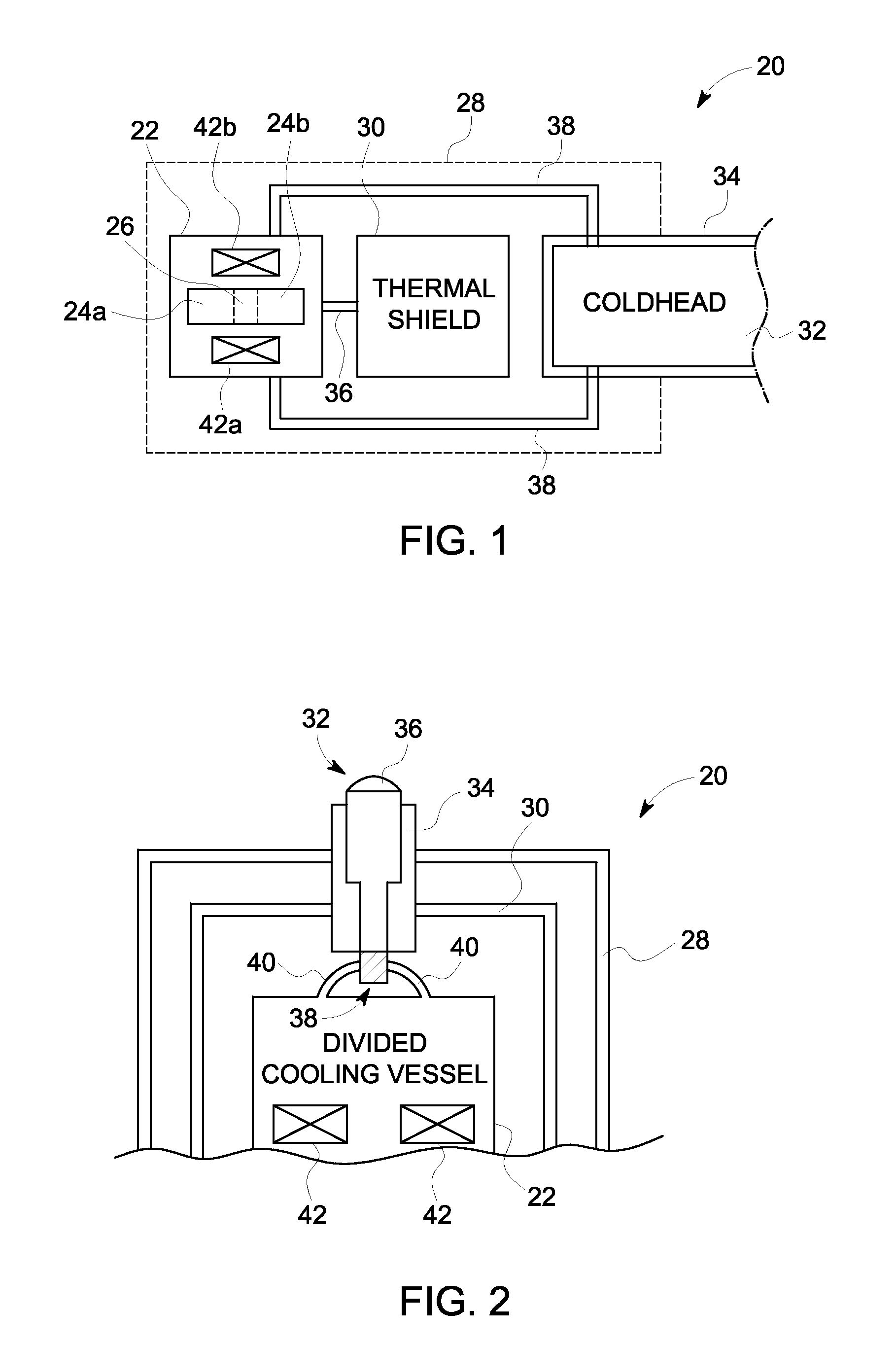
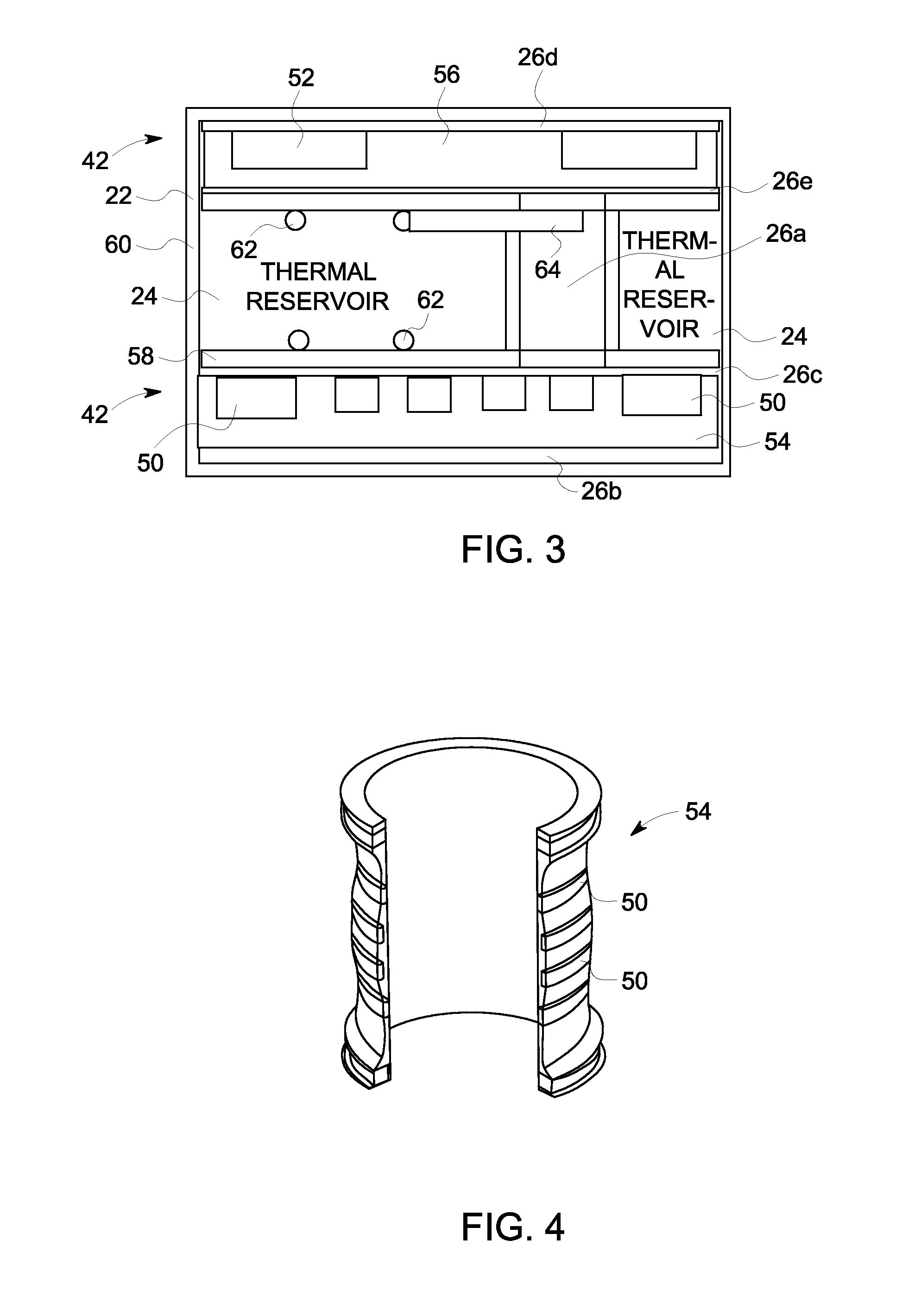
[0017]The foregoing summary, as well as the following detailed description of certain embodiments, will be better understood when read in conjunction with the appended drawings. To the extent that the figures illustrate diagrams of the functional blocks of various embodiments, the functional blocks are not necessarily indicative of the division between hardware. Thus, for example, one or more of the functional blocks may be implemented in a single piece of hardware or multiple pieces of hardware. It should be understood that the various embodiments are not limited to the arrangements and instrumentality shown in the drawings.

[0018]As used herein, an element or step recited in the singular and proceeded with the word “a” or “an” should be understood as not excluding plural of said elements or steps, unless such exclusion is explicitly stated. Furthermore, references to “one embodiment” are not intended to be interpreted as excluding the existence of additional embodiments that also i...


PUM

PropertyMeasurementUnit
Temperatureaaaaaaaaaa
Volumeaaaaaaaaaa
Circumferenceaaaaaaaaaa

Abstract

A magnetic resonance imaging (MRI) system with a thermal reservoir and method for cooling are provided. A cooling vessel for a magnet system of the MRI system includes a first portion containing a helium cryogen in contact with a plurality of magnet coils of an MRI system. The cooling vessel also includes a second portion separate from and fluidly decoupled from the first portion, with the second portion containing a material different than the helium cryogen and having a volume greater than the first portion.

Description

BACKGROUND OF THE INVENTION[0001]The subject matter disclosed herein relates generally to cryogenically cooled magnetic resonance imaging (MRI) systems, and more particularly to systems and methods for cooling the magnet coils of the MRI systems.[0002]In superconducting coil MRI systems, the coils forming the superconducting magnets are typically cryogenically cooled using a helium vessel. In these conventional MRI systems, the superconducting coils are cooled in a bath of liquid Helium (He), such that the coils are immersed in the liquid He. This cooling arrangement requires the use of an extremely large high pressure vessel that contains a significant amount of liquid He (e.g., 1500-2000 liters of liquid He). The resulting structure is not only expensive to manufacture, but heavy.[0003]Additionally, in some instances the helium vessel may not be completely filled, such as to save cost. In this situation, portions of the wires forming the coils of the MRI superconducting magnet wil...

Claims


Application Information

Patent Timeline
IPC IPC(8): G01R33/44B23P15/26F25B19/00
CPCH01F6/04Y10T29/49359G01R33/3804H01F6/00G01R33/3802F17C13/007F17C3/085F17C13/001
Inventor JIANG, LONGZHISTAUTNER, ERNST WOLFGANGSCATURRO, JR., JOHNEINZIGER, WILLIAM LOUIS
Owner GENERAL ELECTRIC CO
Why Eureka
Try Eureka