Photography stand

a technology for photography and stands, applied in the field of photography stands, can solve the problems of requiring much painstaking work, requiring a lot of painstaking work, and using a spindle-based turntable to rotate a subject,

Inactive Publication Date: 2012-07-12
JANCOURTZ JOSHUA MORGAN
View PDF5 Cites 20 Cited by
  • Summary
  • Abstract
  • Description
  • Claims
  • Application Information

AI Technical Summary

Benefits of technology

[0010]The present invention therefore provides an apparatus for multi-angle imaging comprising a transparent platform with a center area to support a subject and a platform support structure that rotatively supports the platform outside its center area such that a camera may be positioned longitudinally around the platform without the platform support structure visually interfering with the image around the subject. Some embodiments allow for the support structure to be present below the platform on the side of the platform's rotational axis where a camera will be placed so that there will be no visual interference from the support structure behind or in front of the subject as long as the camera is placed above the platform surface.
[0023]The apparatus therefore provides a “safe zone” adjacent to a plane through the platform's rotational axis where a camera may be placed and aimed at a subject so that the camera's field of view may comfortably fit the subject without visually interfering in a “usable image area” around a subject either in front of or behind the subject. This method allows the resulting image to be cropped as desired so that it includes the subject but not the platform structure. A “safe zone” may therefore be defined as the collection of “usable image areas” throughout a range of angles.

Problems solved by technology

This can require much painstaking work, requiring adjustments to camera settings and position, light orientation and background adjustments to ensure uniformity for all images.
Attempting to capture multi-angle images when using these types of non-opaque platforms presents significant challenges: using a spindle-based turntable to rotate a subject may be unsatisfactory due to visual interference from a spindle or surrounding rotation mechanism, and manually moving the subject on the platform or moving the platform itself can require much painstaking work in order to achieve consistent results.
U.S. Pat. No. 6,343,184, Huebner discloses a transparent stage rotatably connected to a stage support and a method of moving a camera horizontally and vertically with respect to the stage, however Huebner fails to disclose a stage support that will not be visible either directly in front of or directly behind the central subject placement area of the stage as a camera is rotated longitudinally about the stage within a full or partial range of angles from one pole of the stage's rotational axis to the other.
Huebner also discloses a means of raising or lowering a stage in order to align a camera with a subject, but suggests a pedestal embodiment and does not disclose a means of supporting the stage such that use of a transparent stage would be possible without any structural elements of the apparatus being visible either directly in front of or directly behind the central subject placement area of the stage as a camera is rotated longitudinally about the stage within a full or partial range of angles from one pole of the stage's rotational axis to the other.
However, in each of these cases, a spindle or similar apparatus is positioned underneath the support base, greatly hindering the ability to prevent such apparatuses from visually interfering with the image when using a non-opaque platform to hold a subject.

Method used


Image

  • Photography stand
  • Photography stand
  • Photography stand

Examples


Embodiment Construction

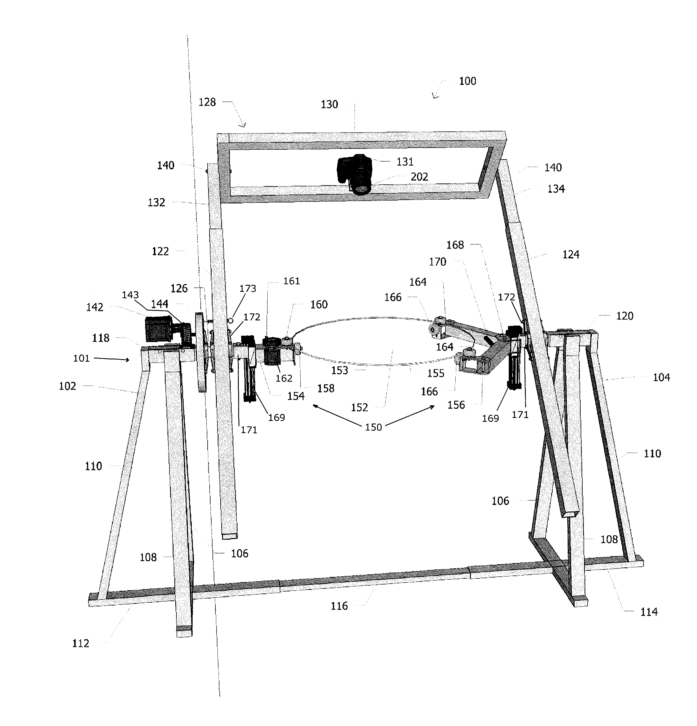
[0045]Referring initially to FIG. 1 shows a front view of the product photography structure 100 according to the present invention. The structure includes several major subassemblies which shall be described in turn.

[0046]Platform support structure 101 comprises a base subassembly and subject platform subassembly. The base subassembly includes a first 102 and second 104 leg support. The leg support as depicted includes three triangulated leg stanchions 106, 108 and 110, connected to cross members 112 and 114 respectively. Cross members 112 and 114 are depicted as being connected by bracket 116 although bracket 116 is not a necessary part of the base subassembly and may be removed without compromising the stability, strength or purpose of the structure. In addition, while the base subassembly is described as having a particular arrangement of leg stanchions and cross members, such arrangement is not required for the operation and purpose of the present invention. Other suitable arran...


PUM


Abstract

An apparatus comprising a platform with a center area and a platform support structure rotatively supporting said platform from outside a safe area adjacent to a plane through said platform's rotational axis whereby an image capture device may be positioned longitudinally throughout a range of angles within the safe area about a subject placed on said platform's center area such that the platform support structure will not substantially interfere visually with the imaging of the subject by appearing in said image capture device's field of view in front of or behind the subject.

Description

CROSS REFERENCE TO RELATED APPLICATIONS[0001]The present application is a continuation-in-part of Patent Cooperation Treaty (PCT) International Application Serial No. PCT / US2010 / 049344 filed on Sep. 17, 2010, which claims the benefit of priority to U.S. Provisional Application Ser. No. 61 / 276,888 filed on Sep. 17, 2009, the entirety of both disclosures being incorporated by reference herein.FIELD OF THE INVENTION[0002]The present invention relates to a physical support structure for use in multi-angle imaging and surface contour data collection of three dimensional objects.STATEMENT OF THE PROBLEM[0003]Studio photography requires a precisely controlled photographic environment in order to achieve consistent and acceptable results in photographing items for use in advertisements, Web sites, and other display media. This is especially true with regard to certain types of product photography wherein multiple angles of a particular item are captured for use in providing an interactive d...

Claims


Application Information

Patent Timeline
Patent Type & Authority Applications(United States)
IPC IPC(8): G03B15/00
CPCF16M11/08G03B15/00
Inventor JANCOURTZ, JOSHUA MORGAN
Owner JANCOURTZ JOSHUA MORGAN
Why Eureka
Try Eureka