Goggle attachment system for a protective helmet
Active Publication Date: 2012-07-19
SMITH OPTICS
16 Cites 26 Cited by
AI-Extracted Technical Summary
Problems solved by technology
Significant injury can result if the head and eyes are not protected.
For example, goggles may be designed so that the goggle may fit comfortably on the face although a helmet may otherwise interfere with the positioning of the goggle on the wearer's face and the positioning of...
Method used
[0014]FIG. 2A illustrates a strap connector 30 and anchor 50 according to an embodiment of the invention. The strap connector 30 includes a strap pull 32 and a post 34 that is attached to the strap pull 32. The post 34, as shown in the embodiment of FIG. 2A may be attached to the strap pull 32. In some embodiments, the post 34 is integrally formed with the strap pull 32. The anchor 50 is configured to receive and pivotally secure the post 34. The anchor 50 of the embodiment illustrated in FIG. 2A includes an anchor fitting 52, and an anchor clip 54 and anchor cover 56. The anchor cover 56 engages the anchor fitting 52 to retain the anchor clip 54 in the anchor fitting 52. In some embodiments, magnets are included in post 34 and the anchor cover 56 to facilitate positioning of the post 34 proximate the anchor 50 and guide the post 54 into the anchor opening 55 to be clipped in the anchor 50. Examples of mechanisms utilizing a clip and cover, for example, anchor clip 54 and anchor cover 56, and magnetic attraction to help guide a post into a latch are designed and manufactured by Fidlock GmbH, for example, as described in International Patent Publication WO2008/006357 and WO2009/092368.
[0020]When positioned in the opening 12, as shown in FIG. 3B, the detachment channel 55 is oriented to line up with the recess 14, for example, in-line with a longitudinal axis 11 of the recess 14. This may facilitate detaching the strap connector 30 from the anchor 50 when it is pulled in a direction along the detachment channel 55, for example, direction B shown in FIG. 3B. In some embodiments, the recess 14 may be angled downward, for example, relative to a horizontal plane of the helmet when the helmet is worn, to further facilitate detachment of the post (and the strap connector 30) from the anchor 50.
[0021]The anchor 50 may fit in the opening 12 and the recess 13 so that the anchor fitting 52 is recessed relative to an outer surface of the helmet 10 and the beveled surface 53 provides a relatively smooth transition from the helmet surface to the anchor 50. In addition to being esthetically pleasing, such a configuration of the anchor fitting 52, and opening 12 and recess 13, results in a profile for the anchor 50 that may reduce surface abruptness between the anchor 50 and the helmet surface. Additionally, in embodiments having the anchor 50 located on the helmet to receive a post loca...
Abstract
Goggles, protective wear, and methods attaching and detaching a goggle are disclosed. In a described example, protective wear includes a goggle and a helmet. The goggle include first and second strap attachments coupled to a strap. The first strap attachment is pivotally connected to a goggle assembly and the second strap attachment has a post. The helmet includes an anchor positioned in an opening in the helmet and is oriented to position an anchor channel to be in line with a recess formed on an exterior of the helmet. The anchor is configured to receive the post and pivotally secure the post therein to attach the goggle to the helmet. The anchor is further configured to release the post responsive to the second strap attachment pulled in a direction substantially parallel with the anchor channel of the anchor.
Application Domain
GogglesHats +6
Technology Topic
Electrical and Electronics engineeringSafety goggles
Image
Examples
- Experimental program(1)
Example
[0011]The present application describes a goggle attachment system and a method of attaching goggles to helmets. Many specific details of certain embodiments of the invention are set forth in the following description and the Figures provide a thorough understanding of such embodiments. One skilled in the art, however, will understand that the present invention may have additional embodiments and that other embodiments of the invention may be practiced without several of the details and components described in the following description.
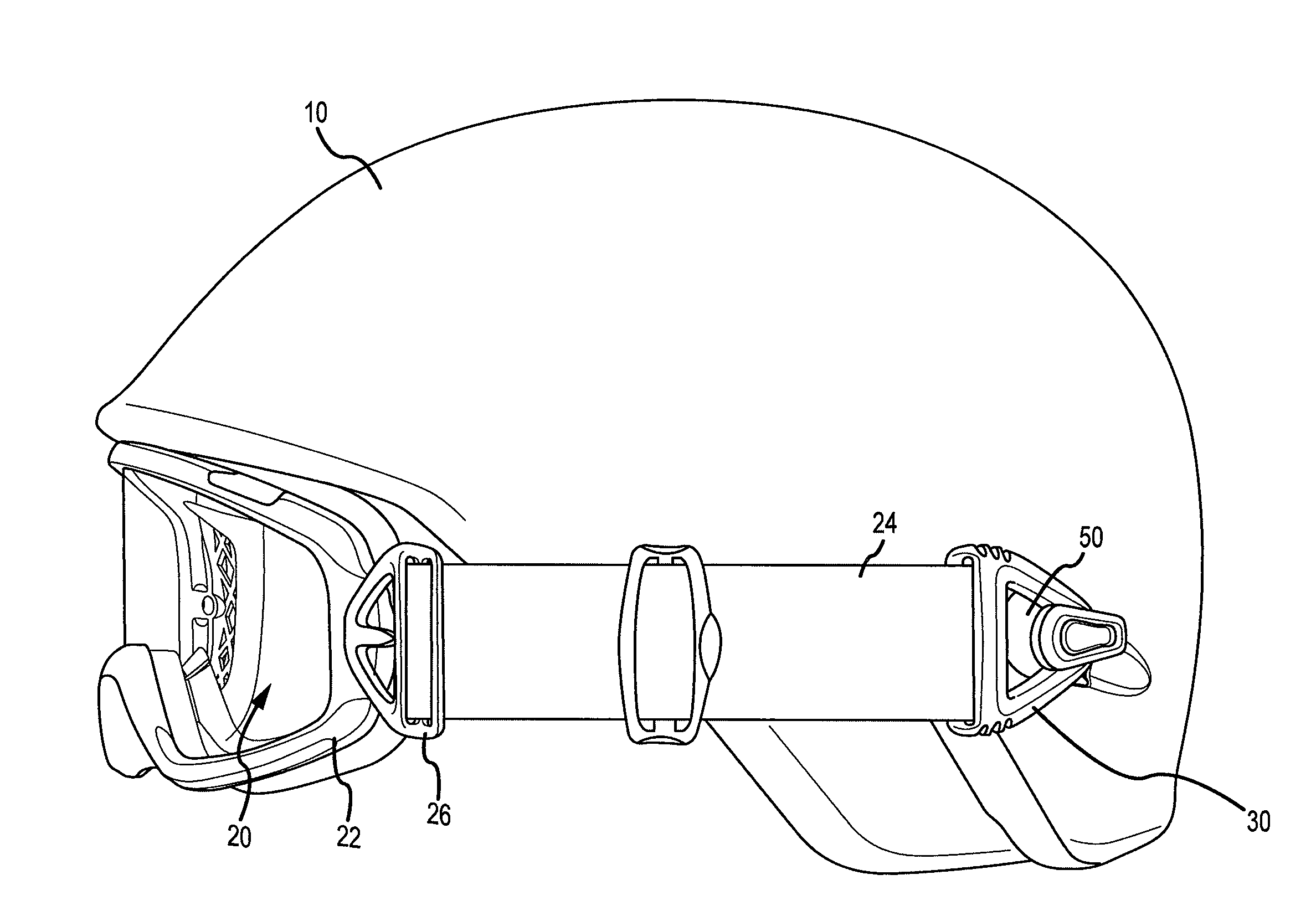
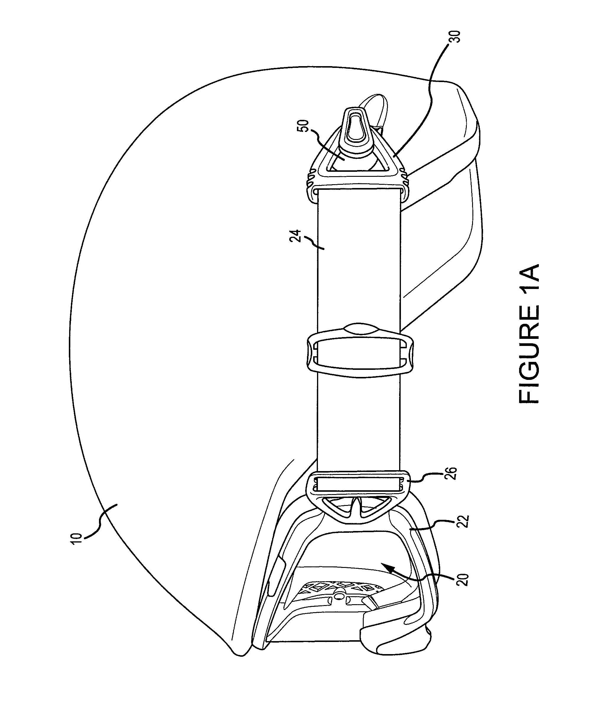
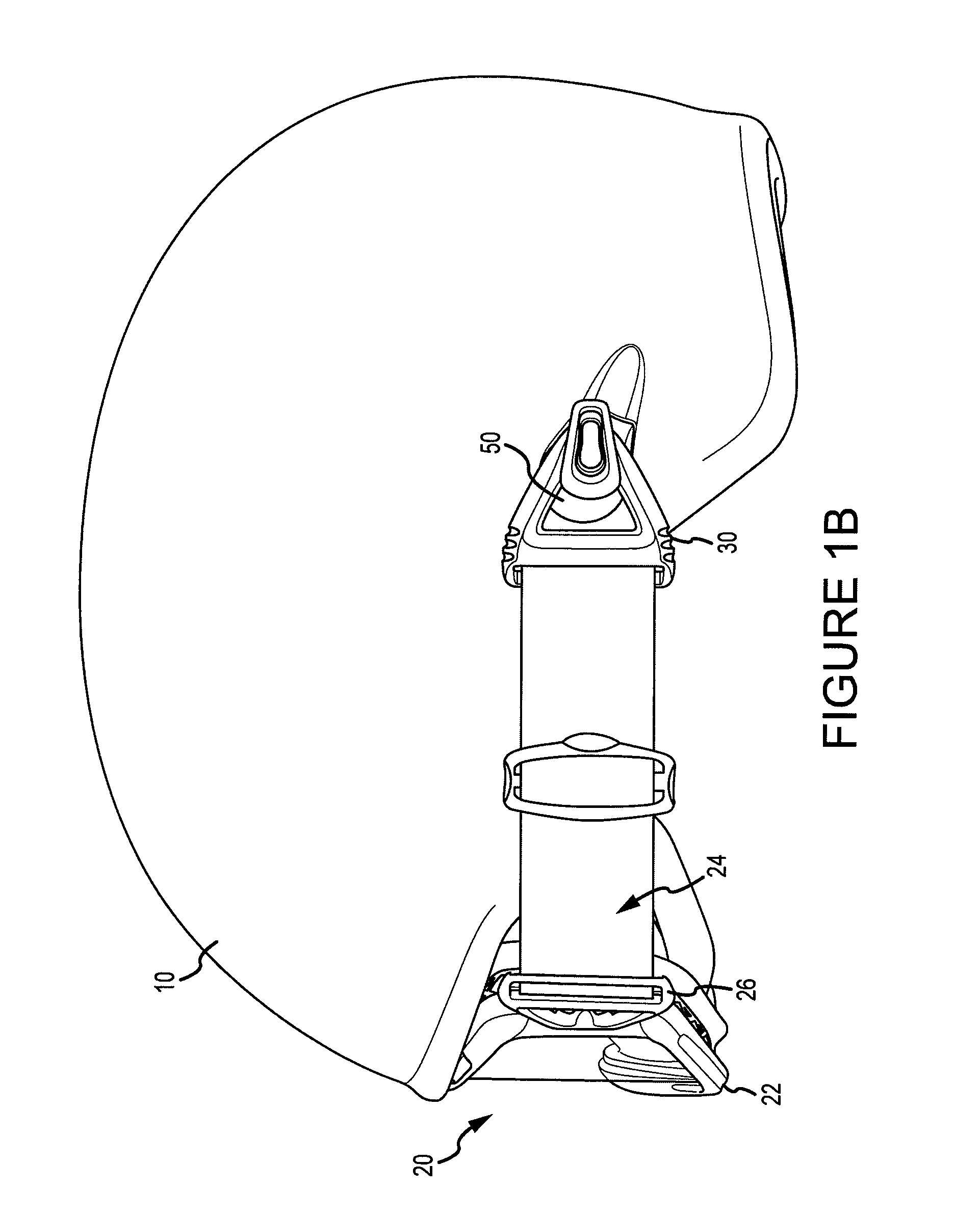
[0012]FIGS. 1A and 1B illustrate a goggle attachment system according to an embodiment of the invention for a helmet 10 and goggle 20. The helmet 10 and goggle 20 may be worn during activities, for example, skiing or snowboarding. Goggle 20 has a lens assembly 22 to which resilient strap 24 is attached by strap connector 26. The resilient strap 24 may be connected to the strap connector 26 by securing the strap 24 through a loop of the strap connector 26. In other embodiments, the strap 24 may be attached to the strap connector 26 by other techniques, for example, molded into the strap connector 26. The strap 24 may be adjustable, for example, using adjustment mechanisms commonly known. The strap connector 26 may be pivotally attached to the lens assembly 22 of the goggle 20, as shown in the embodiment of FIGS. 1A and 1B. A pivotal attachment of the strap connectors 26 to the goggle 20 has a benefit of allowing for the straps 24 to pivot and achieve an angle relative to the lens assembly 22 to comfortably position the goggle 20 on a variety of face shapes and avoid strap binding. Other strap attachment techniques to the lens assembly 22 may be used as well without departing from the scope of the present invention. The lens assembly 22 may be a framed, frameless, or other goggle design. The lens assembly may include a goggle lens and a lens structure attached to the goggle lens which provides attachment to the strap connector 26.
[0013]A strap connector 30 attached to the strap 24 may be, as will be explained in more detail below, removably and pivotally attached to an anchor 50 of the helmet 10. The strap 24 may be connected to the strap connector 30 through a loop of the strap connector 30, molded into the strap connector 26, or other design. In the embodiment illustrated in FIGS. 1A and 1B, the strap 24 is attached to the strap connector 30 through a loop. The opposed dual-pivoting attachment to the lens assembly 22 and of the strap connector 30 to the helmet 10 may allow the goggle to independently adjust to the particularities of a wearers facial features and provide a comfortable fit. Although not illustrated in FIGS. 1A and 1B, a second resilient strap 24 and strap connector 26 are attached to the opposite side of the lens assembly 22 of the goggle 20. In some embodiments, a second anchor 50 is located on the opposite side of the helmet 10 to which a second strap connector 30 is removably and pivotally attached.
[0014]FIG. 2A illustrates a strap connector 30 and anchor 50 according to an embodiment of the invention. The strap connector 30 includes a strap pull 32 and a post 34 that is attached to the strap pull 32. The post 34, as shown in the embodiment of FIG. 2A may be attached to the strap pull 32. In some embodiments, the post 34 is integrally formed with the strap pull 32. The anchor 50 is configured to receive and pivotally secure the post 34. The anchor 50 of the embodiment illustrated in FIG. 2A includes an anchor fitting 52, and an anchor clip 54 and anchor cover 56. The anchor cover 56 engages the anchor fitting 52 to retain the anchor clip 54 in the anchor fitting 52. In some embodiments, magnets are included in post 34 and the anchor cover 56 to facilitate positioning of the post 34 proximate the anchor 50 and guide the post 54 into the anchor opening 55 to be clipped in the anchor 50. Examples of mechanisms utilizing a clip and cover, for example, anchor clip 54 and anchor cover 56, and magnetic attraction to help guide a post into a latch are designed and manufactured by Fidlock GmbH, for example, as described in International Patent Publication WO2008/006357 and WO2009/092368.
[0015]The anchor fitting 52 may include a beveled surface 53, as illustrated in FIG. 2A. The anchor 50 is positioned in an opening 12 formed in the helmet 10. A recess 14 is formed adjacent the opening 12, and as will be explained in more detail below, may facilitate pulling the strap pull 32 and post 34 free from the anchor 50, thereby detaching the strap connector 30 from the helmet 10.
[0016]The anchor fitting 52 may be configured to have an anchor opening 57 that receives the post 34 so that it may be clipped by anchor clip 54. The anchor clip 54 includes a split 58 and is configured to hold the post 34 within the anchor 50 but release the post 34 when it is pulled in a direction through the split 58. When clipped in the anchor 50, the post 34 is secured but is still allowed to rotate within the anchor opening 57 thereby allowing the strap connector 30 to rotate while engaged in the anchor 50. The anchor fitting 52 is further configured to have a detachment channel 55 that allows the post 34 to be pulled free of the anchor 50 so that the strap connector 30 may be detached.
[0017]In operation, to attach the strap connector 30 to the anchor 50, the strap connector 30 is moved in a generally perpendicular direction toward the anchor opening 57, for example, direction A shown in FIG. 2B, until the post 34 is inserted into the anchor opening 57 until the post is engaged and pivotally secured in the anchor 50 (e.g., by anchor clip 54). To detach the strap connector 30, the post is pulled free from the anchor 50 by pulling the strap pull 32 (and thereby the post 34) in a direction generally parallel to the length of the detachment channel 55, for example, direction B shown in FIG. 2C. The post 34 is pulled through the split 58 and released from the anchor clip 54 so that the strap connector 30 can be detached from the helmet 10. In some embodiments, the post 34 may be attached to the anchor 50 in addition or in the alternative to perpendicular insertion into the anchor 50 by sliding the post 34 along the detachment channel 55 into the anchor opening 57 where the post is engaged.
[0018]The previously described embodiment provides an example of an anchor 50 having a specific clip and cover configuration. However, other embodiments may utilize anchors of other designs, for example, rather than the specific configuration of the anchor clip 54 and anchor cover 56 illustrated in FIG. 2A, an anchor can utilize alternatively configured clips and covers. Moreover, the anchor 50 may utilize other mechanisms for receiving, engaging, and pivotally securing the post 34, for example, spring engaged latches, catches, slots, and other mechanisms now known or later developed. Therefore, the invention is not limited to the specific embodiment illustrated and described with reference to FIG. 2A.
[0019]FIG. 3A illustrates the opening 12 of the helmet 10 in which the anchor 50 is positioned. The anchor 50 is shown with anchor fitting 52, anchor clip 54, and anchor cover 56 of FIG. 2A assembled. The anchor 50 fits into the opening 12 with the anchor fitting 52 engaging an anchor fitting recess 13, as shown in FIG. 3B. The opening 12 in which the anchor 50 is positioned may be formed through a shell of the helmet 10 and a cavity formed in a helmet liner. The cavity may partially extend or extend all the way through the helmet liner to house at least a portion of the anchor.
[0020]When positioned in the opening 12, as shown in FIG. 3B, the detachment channel 55 is oriented to line up with the recess 14, for example, in-line with a longitudinal axis 11 of the recess 14. This may facilitate detaching the strap connector 30 from the anchor 50 when it is pulled in a direction along the detachment channel 55, for example, direction B shown in FIG. 3B. In some embodiments, the recess 14 may be angled downward, for example, relative to a horizontal plane of the helmet when the helmet is worn, to further facilitate detachment of the post (and the strap connector 30) from the anchor 50.
[0021]The anchor 50 may fit in the opening 12 and the recess 13 so that the anchor fitting 52 is recessed relative to an outer surface of the helmet 10 and the beveled surface 53 provides a relatively smooth transition from the helmet surface to the anchor 50. In addition to being esthetically pleasing, such a configuration of the anchor fitting 52, and opening 12 and recess 13, results in a profile for the anchor 50 that may reduce surface abruptness between the anchor 50 and the helmet surface. Additionally, in embodiments having the anchor 50 located on the helmet to receive a post located on the strap connector (i.e., part of the goggle) may help eliminate protruding features on the helmet 10.
[0022]FIGS. 4A and 4B illustrate the strap connector 30 according to an embodiment of the invention. A strap pull 32 is configured to have a generally triangularly shape formed from members 35, 36, and 38. The member 38 forms a loop 31 with cross member 37 through which the resilient strap 24 is attached to the strap connector 30. A pull portion 33 of the strap pull 32 may facilitate grabbing of the strap connector 30, for example, to pull the strap connector free of the anchor 50. The pull portion 33 may be formed with ridges on the surface to assist with gripping the strap connector. The post 34 is configured to have a button portion 62 and a groove 64. The button portion 62 may have a beveled surface 63 to facilitate insertion into the anchor 50 and the groove 64 is engaged, for example, anchor clip 54, to clip the post 34 and thereby the strap connector 30 in the anchor 50. As previously described, the post 34 may be attached to the strap pull 32. For example, the post 34 and strap pull 32 may be formed with matching threaded portions (not shown) so that the two are screwed together. In some embodiments, the post 34 may be integrally formed with the strap pull 32.
[0023]FIG. 5 illustrates a goggle attachment system according to an embodiment of the invention. In some embodiments of the invention, the anchor 50 may be positioned on the helmet 10 along a path that naturally extends from the pivot point of the strap connector 26 attached to the lens assembly 22 when the goggle 20 is positioned on the wearer's face such that torque on the lens assembly 22 may be reduced or eliminated to improve fit and comfort of the goggle wearer. For example, as illustrated for the embodiment of FIG. 5, the anchor 50 may be positioned proximate an apex 15 of an ear cutout 16 of helmet 10. The anchor 50 may be positioned rearward and proximate the apex 15 in FIG. 5. In some embodiments, the anchor 50 is positioned so that when the post 34 is engaged in the anchor 50 the strap connector 30 pivots around a point that is approximately in line with an edge 17 of the ear cutout 16, or slightly above a ray extending along the edge 17. The position of the anchor 50 may also result in the goggle strap 24 being substantially horizontal when the goggle 20 is positioned on the wearer's face.
[0024]From the foregoing it will be appreciated that, although specific embodiments of the invention have been described herein for purposes of illustration, various modifications may be made without deviating from the spirit and scope of the invention. For example, although specific embodiments described herein have the post attached to the strap connector and the anchor located on the helmet, in other embodiments the post may be located on the helmet and the anchor that receives and engages the post is attached to the strap connector. Moreover, specific embodiments described herein include the anchor located on the exterior of the helmet. However, in alternative embodiments, the anchor may be positioned on an interior of the helmet to receive and engage the strap connector to attached the goggle to the helmet. Accordingly, the invention is not limited except as by the appended claims.
PUM
Property | Measurement | Unit |
Shape |
Description & Claims & Application Information
We can also present the details of the Description, Claims and Application information to help users get a comprehensive understanding of the technical details of the patent, such as background art, summary of invention, brief description of drawings, description of embodiments, and other original content. On the other hand, users can also determine the specific scope of protection of the technology through the list of claims; as well as understand the changes in the life cycle of the technology with the presentation of the patent timeline. Login to view more.