
Interpolation

a technology of interpolation and image, applied in the field of interpolation, can solve the problems of image feature not being detected in the resulting greyscale image, low image detail, etc., and achieve the effect of improving the detail level

Inactive Publication Date: 2012-07-19
SONY CORP
View PDF4 Cites 16 Cited by
  • Summary
  • Abstract
  • Description
  • Claims
  • Application Information

AI Technical Summary

Benefits of technology

[0016]This process therefore aims to boost detail level which would be hidden during standard conversion methods. More generally, the arrangement aims to vary the relative proportions of the colour components in a monochromatic test pixel so that colour components with higher image activity contribute a generally higher proportion of the monochromatic test pixel, for example by modifying a set of coefficients defining the contribution of each colour component to a monochromatic pixel in dependence upon the detected image activity relating to that colour component.

Problems solved by technology

A problem can arise in areas of low image detail.
However, using fixed coefficients in this way, two very different colours in the GBR colour space could produce identical greyscale colours, and therefore a particular image feature might not be detected in the resulting greyscale image.

Method used


Image

  • Interpolation
  • Interpolation
  • Interpolation

Examples


Embodiment Construction

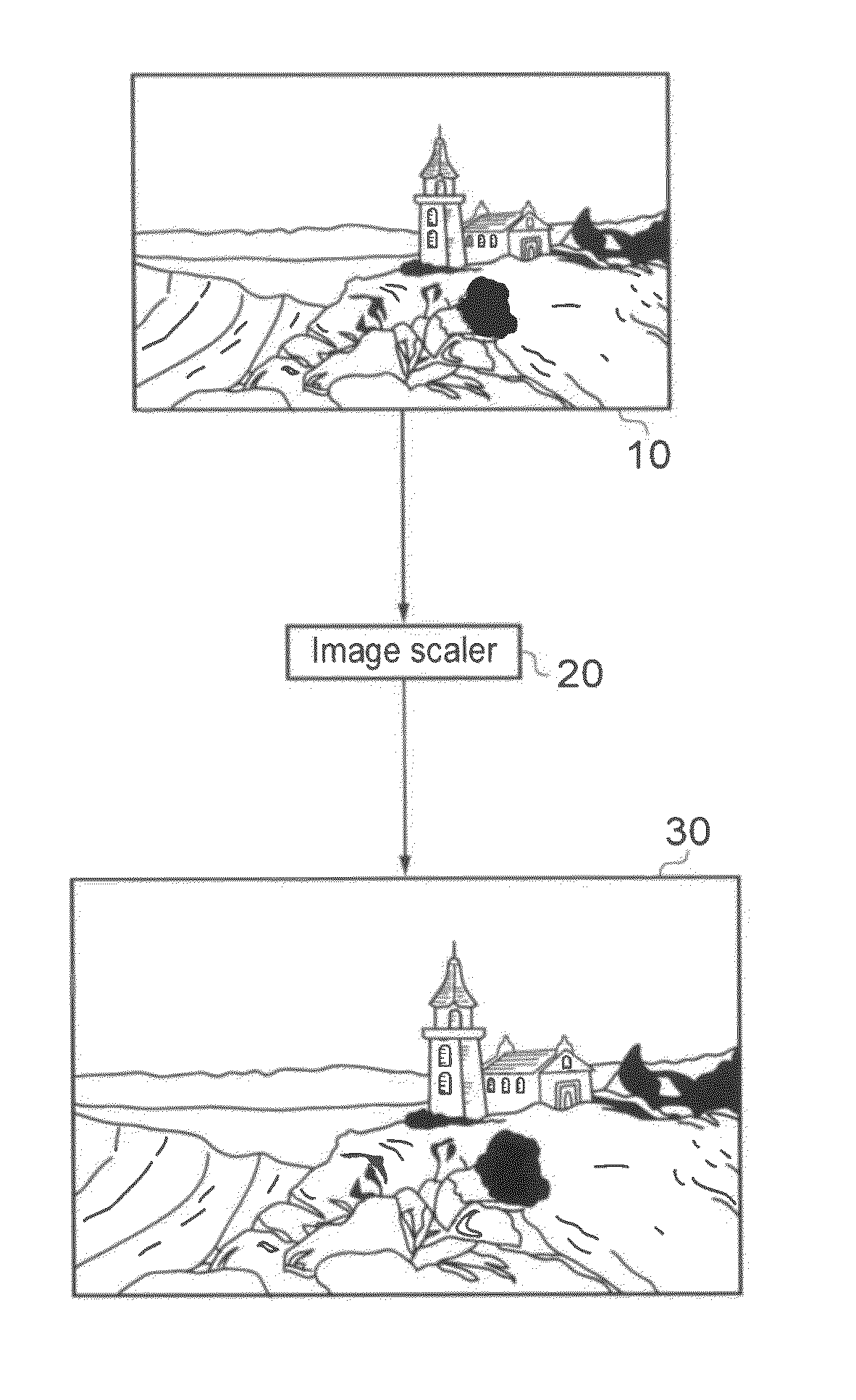
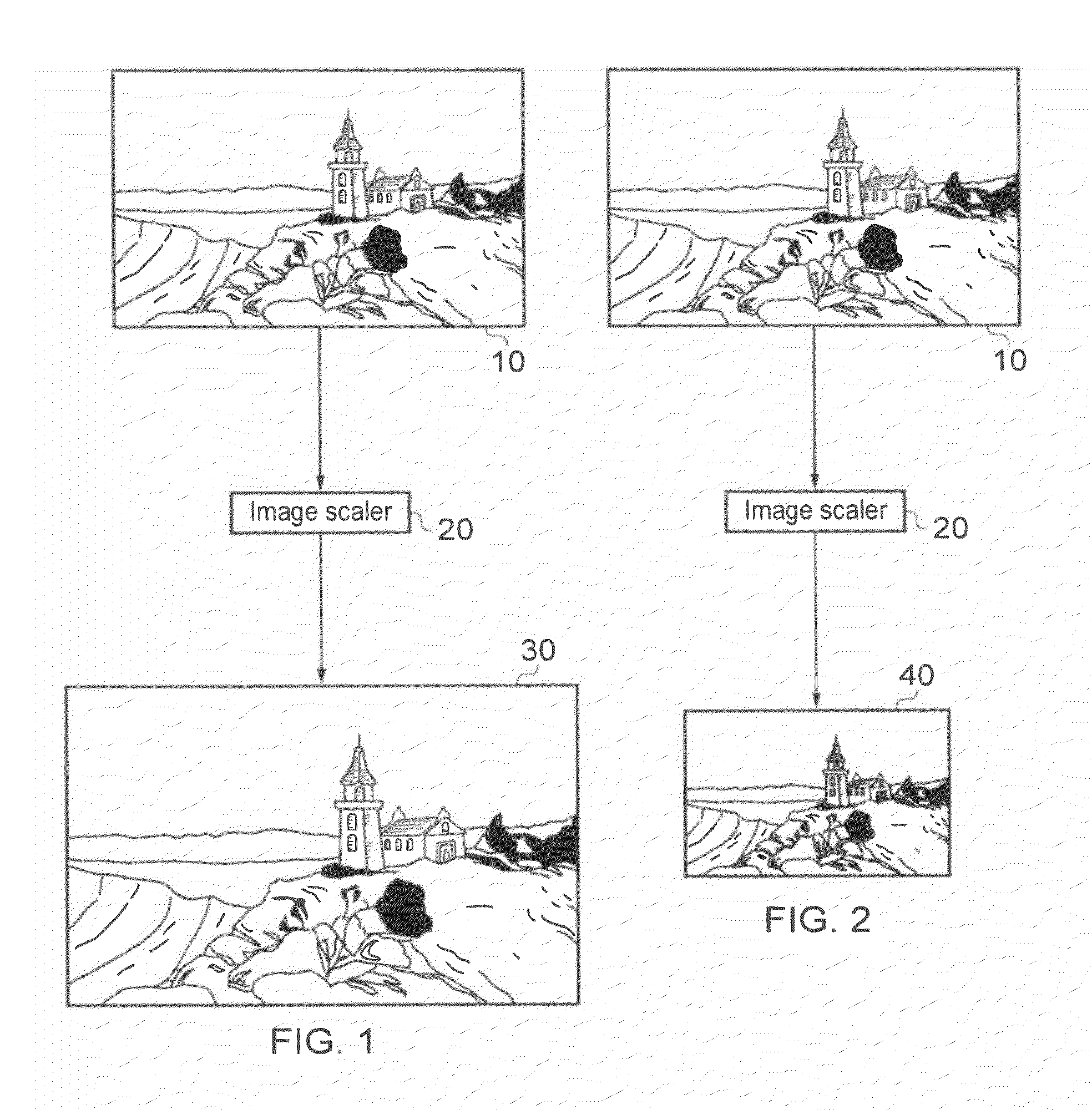
[0051]Referring now to the drawings, FIGS. 1 and 2 schematically illustrate an image scaling process, as applied to a source image 10. In each case the source image (a two-dimensional array of input pixels) 10 is processed by an image scaling apparatus 20, to generate a larger output image 30 (FIG. 1) or a smaller output image 40 (FIG. 2) formed of output pixels. Here, the terms “larger” and “smaller” refer to the number of pixels in the respective output images, rather than to a format in which the images are actually displayed. So, for example, if the input image has 1920 (horizontal)×1080 (vertical) pixels, the larger output image 30 might have 2880×1620 pixels, and the smaller output image 40 might have 960×540 pixels. Clearly, these pixel numbers are just examples, and in general the image scaler 20 can operate to scale the image across a range of scale factors which may include scale factors greater than one (for image enlargement) and / or scale factors less than one (for image...


PUM


Abstract

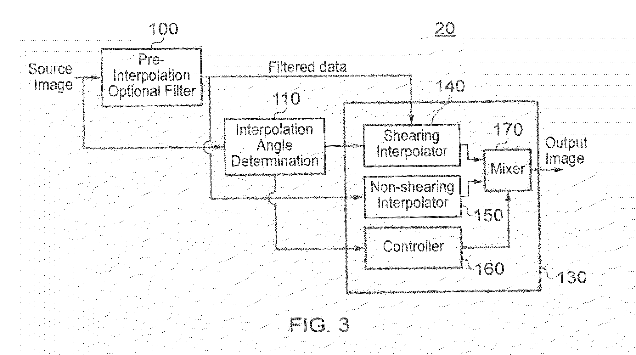
A method of pixel interpolation in which a two-dimensional digital filter is arranged so as to interpolate an output pixel from a two-dimensional array of colour input pixels by aligning a filtering operation with a detected direction of an image feature at a pixel position to be interpolated comprises detecting image activity within respective colour components of a group of input pixels around the pixel position to be interpolated; generating monochromatic test pixels by combining the colour components of input pixels in relative proportions dependent upon the detected image activities; detecting the direction of an image feature in a group of the monochromatic test pixels around the pixel position to be interpolated; and interpolating an output pixel using the two-dimensional filter, according to the detected image feature direction.

Description

BACKGROUND OF THE INVENTION[0001]1. Field of the Invention[0002]This invention relates to interpolation.[0003]2. Description of the Prior Art[0004]Pixel interpolation techniques have been proposed, for use in image or video processing systems, in which the interpolation of output pixels from input pixels depends on the detected directions of image features around the input pixels. It has been proposed that the detection of the direction or angle of such image features can be carried out by finding a direction of lowest variance amongst the input pixels.[0005]The angle detection process can be conducted (for example) on a greyscale (monochromatic) version of the input pixels or separately on each GBR (green, blue, red) component of the input pixels. If the latter is used, then the GBR results can be combined (e.g. according to the standard ratios of G, B and R used in the generation of a luminance (Y) value) so as to generate a single output result. It is desirable to operate on mono...

Claims


Application Information

Patent Timeline
Patent Type & Authority Applications(United States)
IPC IPC(8): G06K9/00
CPCG06T7/403G06T3/4007G06T7/44G06T7/13G06T7/90G06T3/403
Inventor SHARMAN, KARLPINDORIA, MANISH DEVSHI
Owner SONY CORP
Learn More