Connector

a technology of connecting rods and connectors, applied in the direction of three-pole connections, coupling device connections, electric discharge lamps, etc., can solve the problems of poor bundling workability in the above structure, and achieve the effect of easy bundling and easy insertion

Inactive Publication Date: 2012-07-19
HITACHI CABLE
View PDF0 Cites 7 Cited by
  • Summary
  • Abstract
  • Description
  • Claims
  • Application Information

AI Technical Summary

Benefits of technology

[0011]However, the above structure is poor in the bundling workability since the plural cables are arranged along the lamination direction in correspondence with the lamination direction of the connecting terminals, i.e., the plural cables being in planar arrangement. Thus, it is desired that the plural cables can be conclusively bundled for taking the cabling property into account when used for a wire harness. In addition, the bundled cables are advantageous because it can be easily inserted into a protection member such as aluminum pipe or corrugated tube.
[0025]According to one embodiment of the invention, a connector is constructed such that three first connecting terminals (aligned and housed in a first terminal housing) and three second connecting terminals (aligned and housed in a second terminal housing) are each arranged in the form of a triangle when viewed in the fitting direction of the first terminal housing and the second terminal housing. As a result, three cables each connected to the first and / or second connecting terminals are arranged in the form of the triangle when viewed in the fitting direction. This allows the three cables led out from the connector to be easily bundled together. Thus, the bundled cables can be easily inserted into a protection member with a cylindrical shape such as aluminum pipe or corrugated tube.

Problems solved by technology

However, the above structure is poor in the bundling workability since the plural cables are arranged along the lamination direction in correspondence with the lamination direction of the connecting terminals, i.e., the plural cables being in planar arrangement.

Method used


Image

  • Connector
  • Connector
  • Connector

Examples


Embodiment Construction

[0035]A preferred embodiment of the invention will be described below in conjunction with the appended drawings.

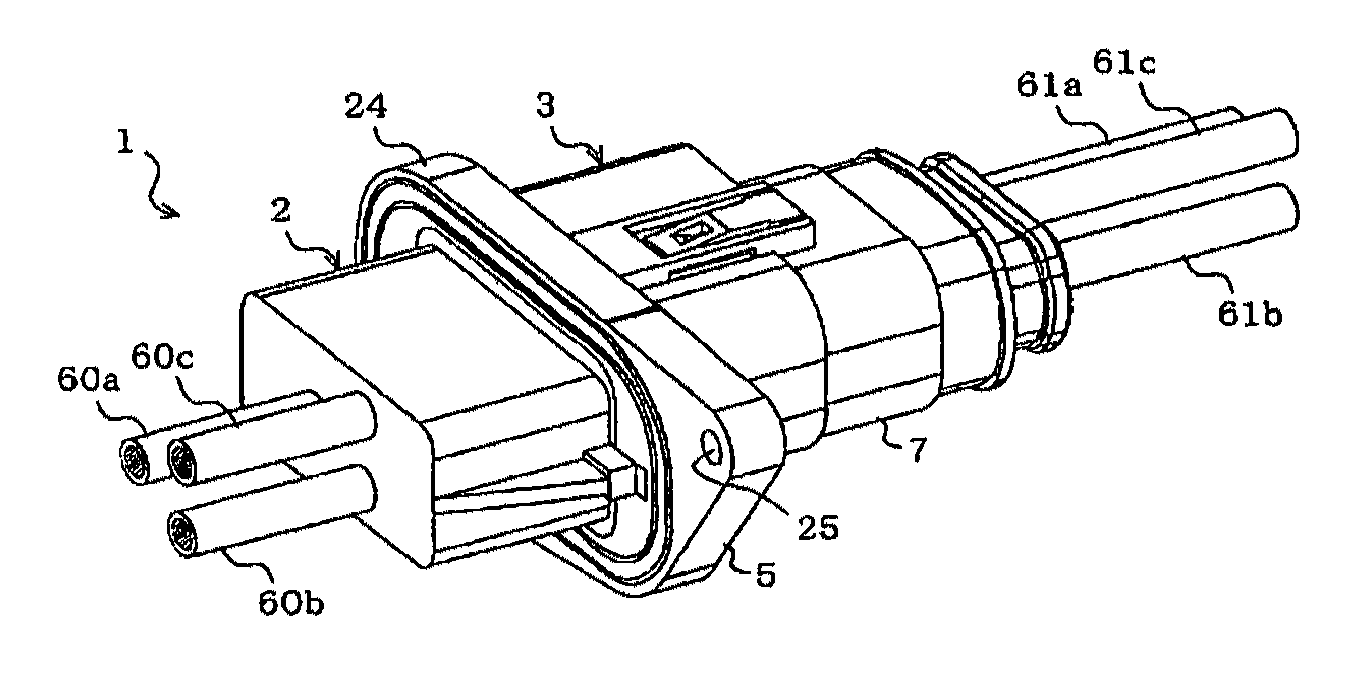
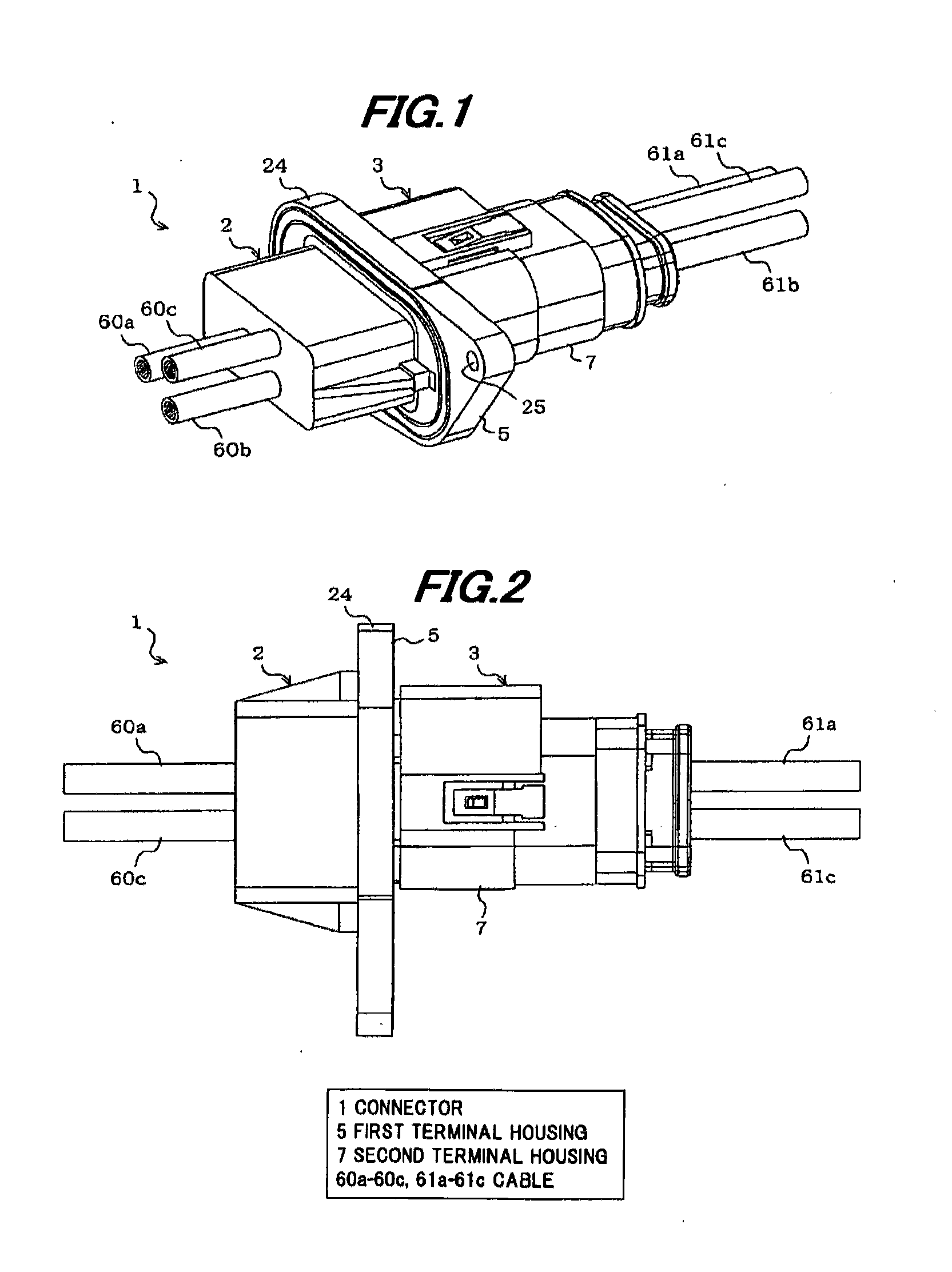
[0036]FIGS. 1 and 2 are diagrams illustrating a connector in the present embodiment, wherein FIG. 1 is perspective view and FIG. 2 is a side view.

[0037]As shown in FIGS. 1 and 2, a connector 1 of the present embodiment is composed of a first connector portion 2 and a second connector portion 3, and three power lines are connected at a time by fitting the connector portions 2 and 3 together.

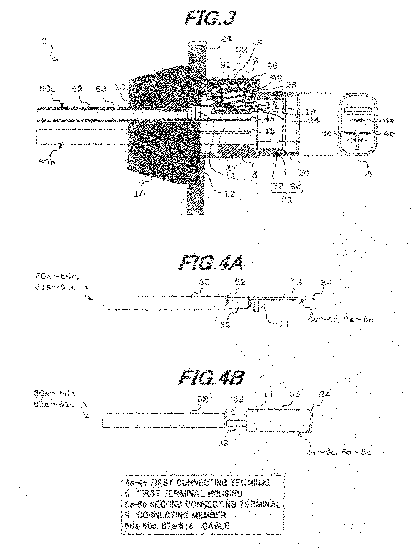
[0038]More specifically, the connector 1 is provided with the first connector portion 2 having a first terminal housing (i.e., male terminal housing) 5 housing three aligned first connecting terminals (i.e., male terminals) 4a to 4c, the second connector portion 3 having a second terminal housing (i.e., female terminal housing) 7 housing plural (three) aligned second connecting terminals (i.e., female terminals) 6a to 6c, and plural (four) insulating members 8a to 8d aligned and housed i...


PUM


Abstract

A connector includes a first terminal housing for housing three first connecting terminals aligned, a second terminal housing for housing three second connecting terminals aligned, a plurality of insulating members that are aligned and housed in the second terminal housing, and a connecting member for collectively fixing and electrically connecting the three first connecting terminals and the three second connecting terminals at each contact point by pressing one of the plurality of insulating members adjacent to the connecting member. The three first connecting terminals and the three second connecting terminals are each arranged in a form of a triangle when viewed in the fitting direction.

Description

[0001]The present application is based on Japanese patent application No. 2011-005828 filed on Jan. 14, 2011, the entire contents of which are incorporated herein by reference.BACKGROUND OF THE INVENTION[0002]1. Field of the Invention[0003]The invention relates to a connector which is used for, e.g., an eco-friendly car such as a hybrid car and an electric car and, in particular, to a connector that may be used as a connecting portion of a power harness used for transmitting a large amount of power.[0004]2. Description of the Related Art[0005]A power harness is used for connecting between devices such as between a motor and an inverter or between an inverter and a battery in, e.g., a hybrid car or an electric car, which has made significant progress in recent years, for transmitting a large amount of power, and a connector in a two-divided structure composed of, e.g., a male connector portion provided with a male terminal as well as a first terminal housing for housing the male term...

Claims


Application Information

Patent Timeline
Patent Type & Authority Applications(United States)
IPC IPC(8): H01R24/28
CPCH01R13/502H01R2105/00H01R24/28H01R24/20
Inventor SUZUKI, SACHIOTAKEHARA, HIDEAKIFUKUDA, KUNIHIROKATAOKA, YUTAUMETSU, JUNHAYASHI, SHINYA
Owner HITACHI CABLE
Why Eureka
Try Eureka