Method of Electricity Distribution Including Grid Energy Storage, Load Leveling, and Recirculating CO2 for Methane Production, and Electricity Generating System

a technology of electricity generation and grid energy storage, applied in steam engine plants, steam generation using hot heat carriers, machines/engines, etc., can solve the problems of slowing the commissioning of new nuclear power plants in the united states, fickle wind power, and inability to generate electricity from wind farms

Inactive Publication Date: 2012-07-26
SCHMIDT ERIC
View PDF3 Cites 17 Cited by
  • Summary
  • Abstract
  • Description
  • Claims
  • Application Information

AI Technical Summary

Benefits of technology

[0007]The present invention is directed generally to a system and method for generating electricity and, more particularly, distributing electricity to consumers via an electrical grid. The present invention is also directed to a system and method of reducing, if not eliminating, certain potentially harmful byproducts of an electric generating system, such as carbon dioxide exhaust of a fossil fuel electric generating plant. In the alternative, the invention provides a system and method for operating a fossil fuel plant utilizing an alternative fuel to fossil fuel and further, to a system and method for generating and distributing electricity, whereby both a fossil-fuel plant and a renewable energy electricity generating station are operated (with the latter being utilized at increased frequency).

Problems solved by technology

In the past, nuclear power was promoted worldwide by many as a cleaner and more efficient energy alternative, but safety concerns and construction difficulties have slowed the commissioning of new nuclear power plants in the United States.
Wind power is fickle, however, and as such, wind farm-generated electricity is not always available.
Engineering design and economics currently do not allow wind turbines to exploit wind energy beyond the 10-12 m / s limit.
Furthermore, even if wind power is available for production, it is not always utilized by the electric grid.
As with all renewable energy electricity sources, wind farm output is often declined by the utility (i.e., curtailed).
In many cases, the utility elects not to throttle down its fossil fuel production, in favor of wind farm production, because the traditional fossil fuel plant cannot readily increase production to meet a sudden grid demand.
Such a sudden grid demand can, of course, be caused by a sudden decrease in wind availability to a wind farm.
In the case of solar power, a sudden change in weather conditions may cause an interruption in output and a corresponding loss of capacity in the grid.
A traditional fossil fuel plant in a state of reduced operating cycle may not be able to ramp up in time to cover the shortfall.

Method used


Image

  • Method of Electricity Distribution Including Grid Energy Storage, Load Leveling, and Recirculating CO2 for Methane Production, and Electricity Generating System
  • Method of Electricity Distribution Including Grid Energy Storage, Load Leveling, and Recirculating CO2 for Methane Production, and Electricity Generating System
  • Method of Electricity Distribution Including Grid Energy Storage, Load Leveling, and Recirculating CO2 for Methane Production, and Electricity Generating System

Examples


Embodiment Construction

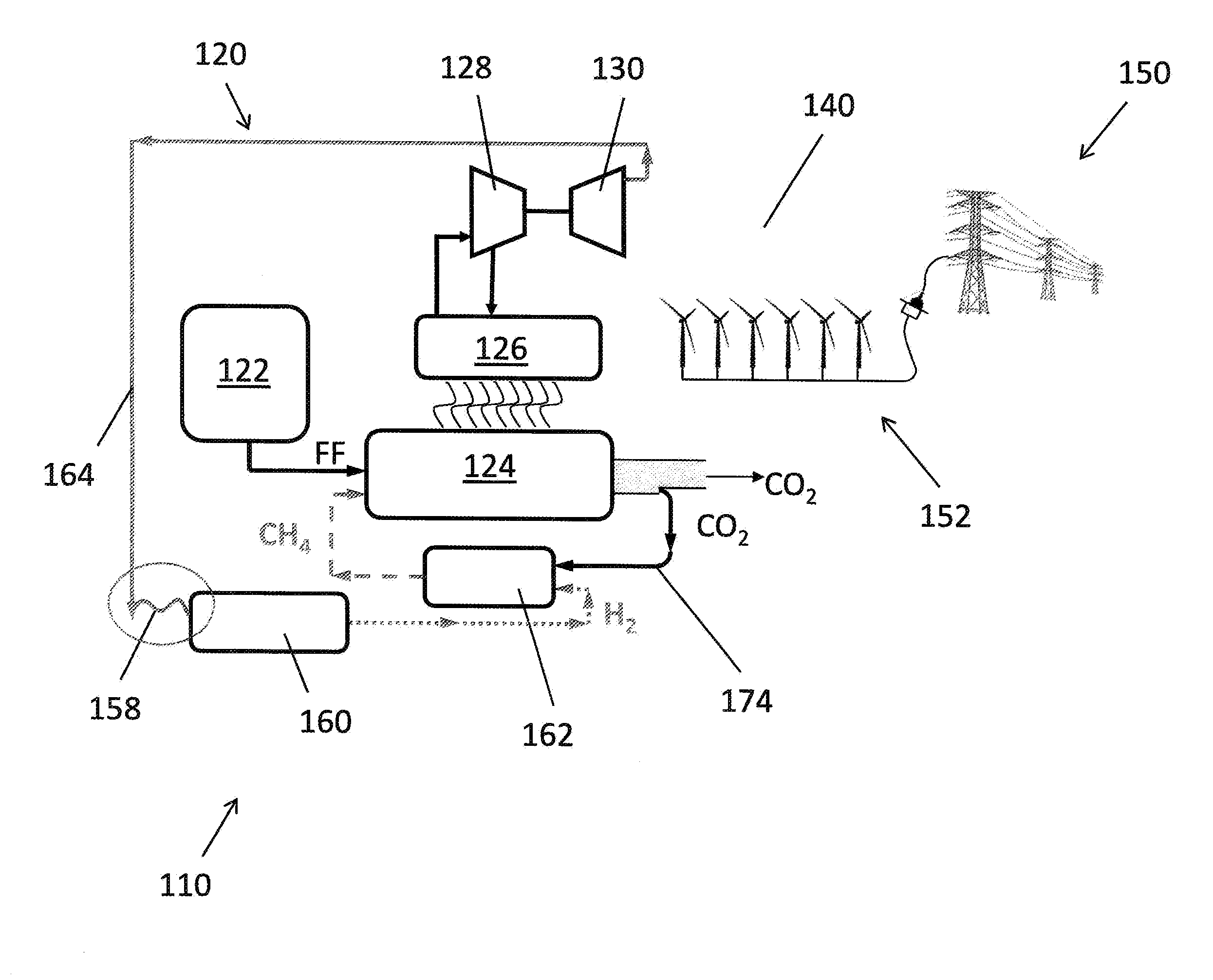
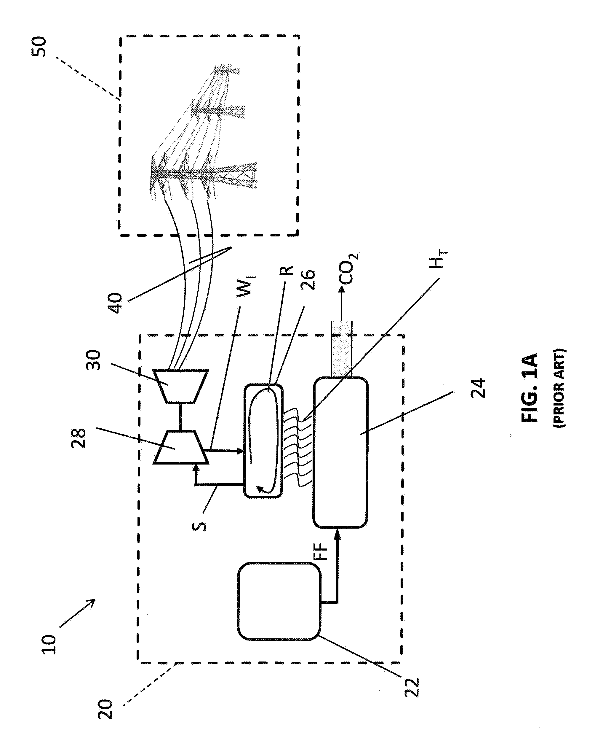
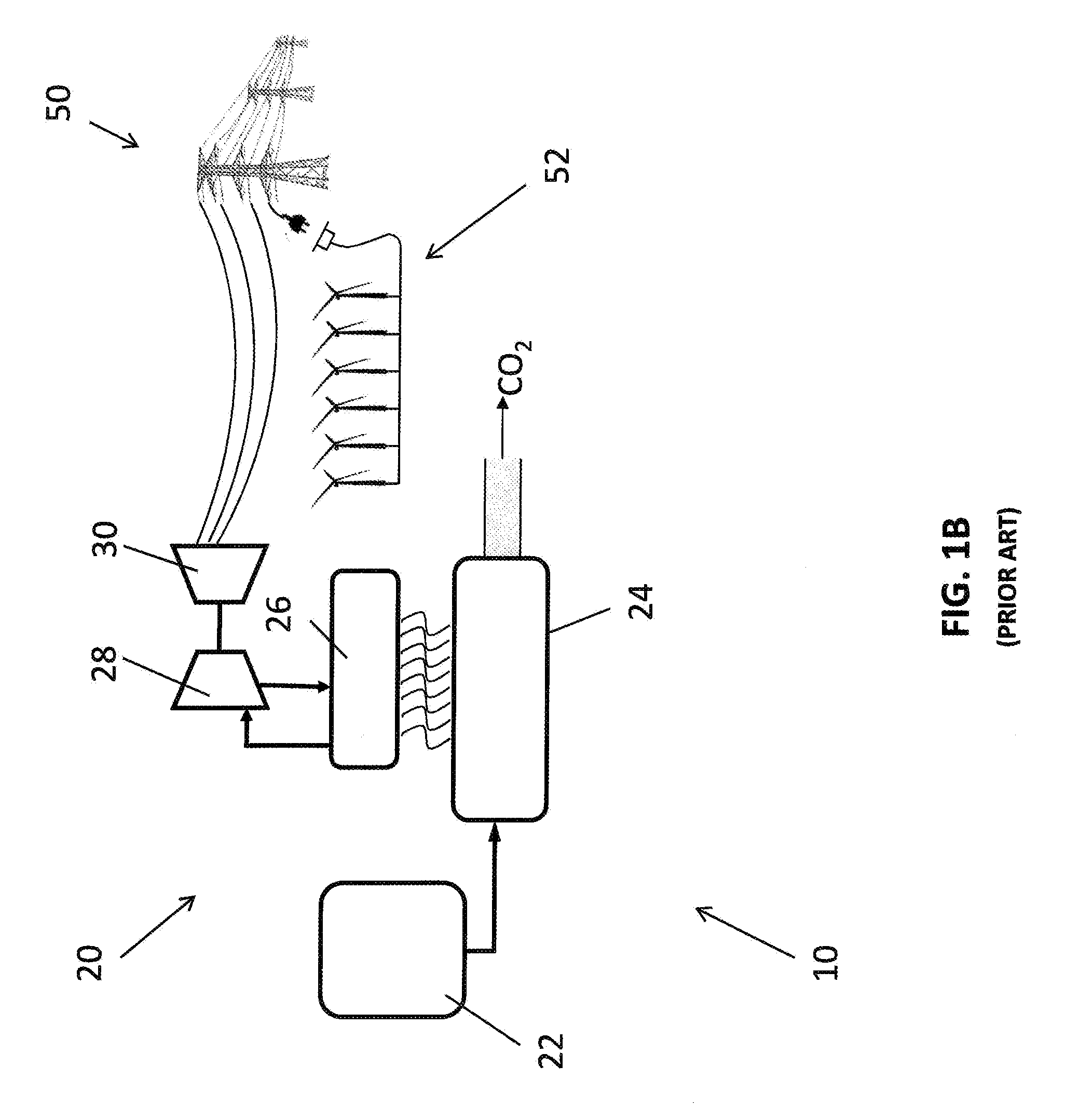
[0023]FIG. 1A is a simplified representation of an electric generating system 10. The electric generating system 10 includes a fossil fuel electric generating plant 20 (or “fossil fuel plant”) that generates electricity by burning a fossil fuel such as natural gas, coal, fuel oil, or other suitable and available fuels. As described in the present disclosure, the electric generating system 10 also provides for the transmission of the generated electricity to commercial and residential consumers. The electric generating system 10 is, therefore, described as including transmission lines 40 and an electrical grid 50 connected to the fossil fuel plant 20 by the transmission lines 40. Further, the electrical grid 50 is interconnected with commercial and residential consumers as well as wholesale consumers that operate local distribution networks. As sometimes used herein for purposes of describing certain aspects of the invention, the term electric generating system 10 may include the tra...


PUM


Abstract

A method is provided for generating and distributing electricity via an electrical grid, wherein a fossil fuel plant and a renewable energy electricity generating station are interconnected with the electrical grid and are both operable to generate electricity output. The electricity output is directed from both the fossil fuel plant and the renewable energy electricity generating station to the electrical grid for distribution. Then, at the fossil fuel plant, at least a portion of the electricity output is directed to within the plant and utilized in generating hydrogen. The method provides further a reacting step wherein the generated hydrogen reacts with carbon dioxide to produce methane. Continued operation of the fossil fuel plant is conducted utilizing the produced methane as fuel, to generate electricity output, and also, capturing carbon dioxide exhaust and utilizing it in the reacting step.

Description

FIELD OF THE INVENTION[0001]The present application claims the benefit of U.S. Provisional Application Ser. No. 61 / 587,548, filed on Jan. 17, 2012 (pending), which disclosure is hereby incorporated by reference for all purposes and made a part of the present disclosure.[0002]The present invention relates generally to a system and method for generating electricity and, further, distributing electricity to consumers via an electrical grid. The present invention also relates to a system and method of reducing potentially harmful exhaust or byproduct (e.g. carbon dioxide exhaust) of an electric generating system. The present invention also relates generally to a system and method for operating a fossil fuel plant utilizing an alternative fuel to fossil fuel and further, to a system and method for generating and distributing electricity, whereby both a fossil fuel plant and a renewable energy electricity generating station are operated (with the latter being utilized at increased frequen...

Claims


Application Information

Patent Timeline
Patent Type & Authority Applications(United States)
IPC IPC(8): F01K25/06F01K13/00
CPCF22B1/18
Inventor SCHMIDT, ERIC
Owner SCHMIDT ERIC
Why Eureka
Try Eureka