Housing with locking structure

a technology of locking structure and housing, which is applied in the direction of furniture parts, mechanical equipment, and casings/cabinets/drawer details to release the snap-fit connection by a tool from outside without damaging the housing, etc., can solve the problems of inability to easily apply the tip to the housing, and achieve the effect of easy disassembly and introduction of the tip

Active Publication Date: 2012-07-26
KONINKLIJKE PHILIPS ELECTRONICS NV
View PDF24 Cites 42 Cited by
  • Summary
  • Abstract
  • Description
  • Claims
  • Application Information

AI Technical Summary

Benefits of technology

[0008]To release the snap-fit connection between the first and the second engaging portion, the flexible snap member can be lifted from the inner wall portion of the second housing part against its restoring force. In the lifted state, the snap-fit connection is released, and both housing parts can easily be disassembled by pulling them apart in the direction opposite to the extension direction of the snap member, i.e. by a movement opposite to the sliding direction to assemble the housing parts.
[0010]Because the release tool is integrated into the housing, no other external tool has to be introduced into the housing to release the locking structure. Consequently the provision of an access for a tool from outside is dispensable. For example, the release tool can be provided as a slider sliding at the bottom of the second housing part against its inner wall portion. An actuating or guiding means for sliding the release tool can be provided. The free end of the tool can also be accessible from an opposite side of the housing which is open or provided to be opened anyway to access the space inside the housing and which can be opened or closed by a lid or the like. At least at the side of the housing where the locking structure is located, the external design of the housing is not affected by the locking structure. Assembling and disassembling the housing can easily accomplished by pushing the two housing parts together to form the snap-fit connection, and using the release tool to unlock the snap-fit connection by lifting the snap member from the inner wall portion.

Problems solved by technology

In cases where a tool is necessary to release the locking structure, there is always the problem that the locking member which has to be released by the tool must be accessible from the outside of the housing.
Although it is easy to arrange such a connection by snap members on the inside of the housing, it is impossible in this case to release this snap-fit connection by a tool from outside without damaging the housing.
However, this construction has the same disadvantage as described above, namely that an opening for introducing the tool is indispensable, and apart from that this solution cannot easily be applied to a housing with two complementary housing parts which have to be connected at the edges of their adjacent wall portions.

Method used


Image

  • Housing with locking structure
  • Housing with locking structure
  • Housing with locking structure

Examples


Embodiment Construction

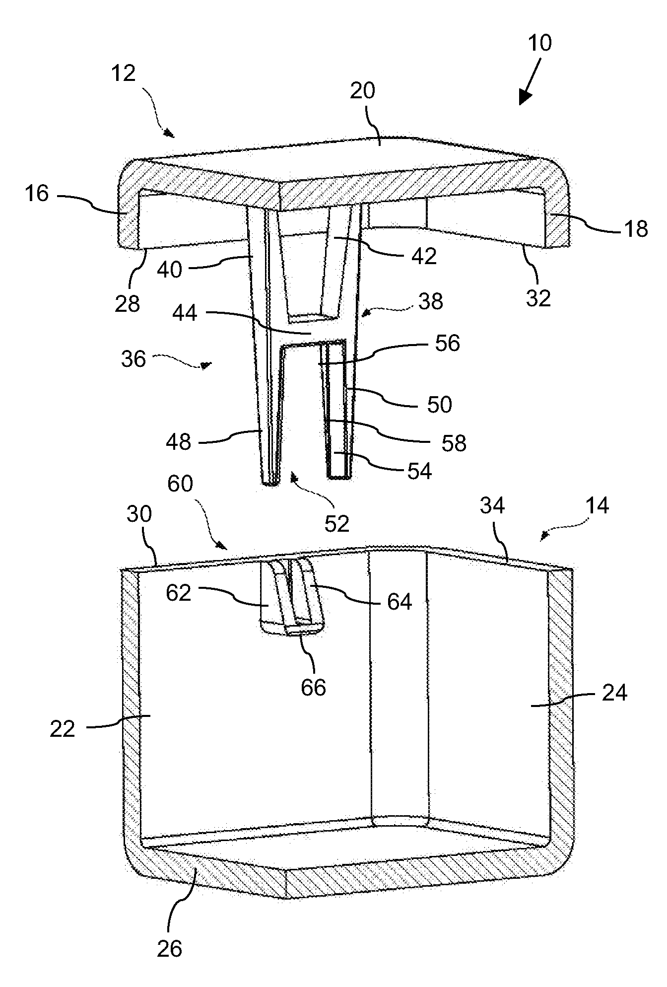
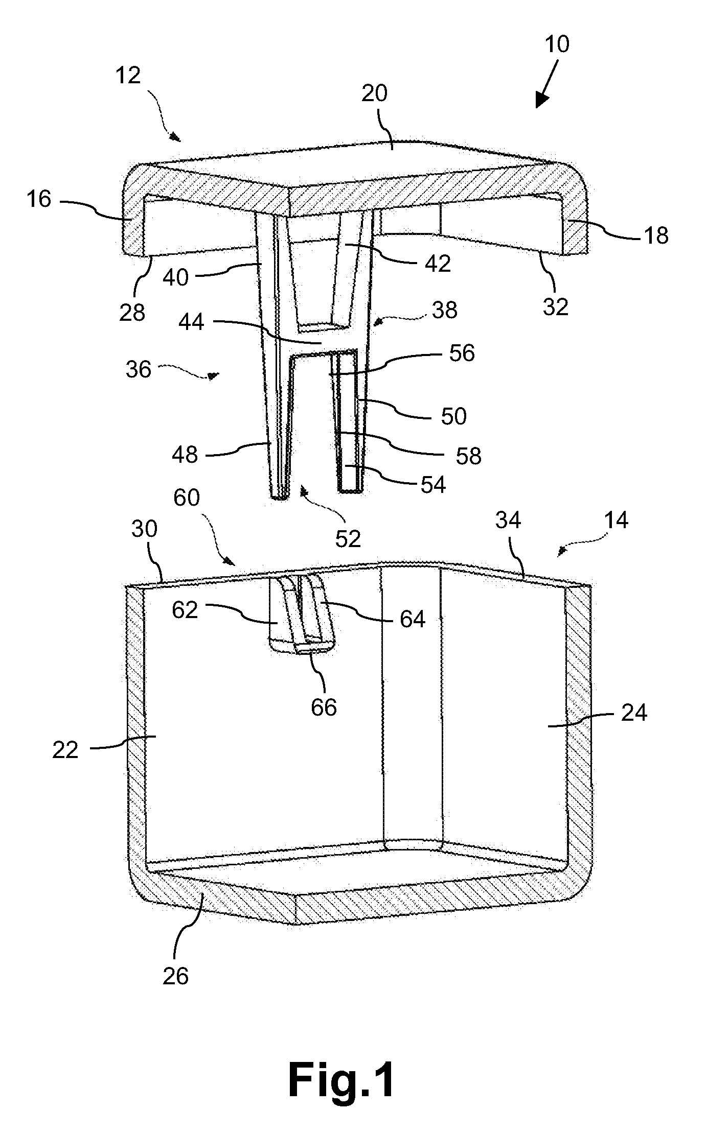
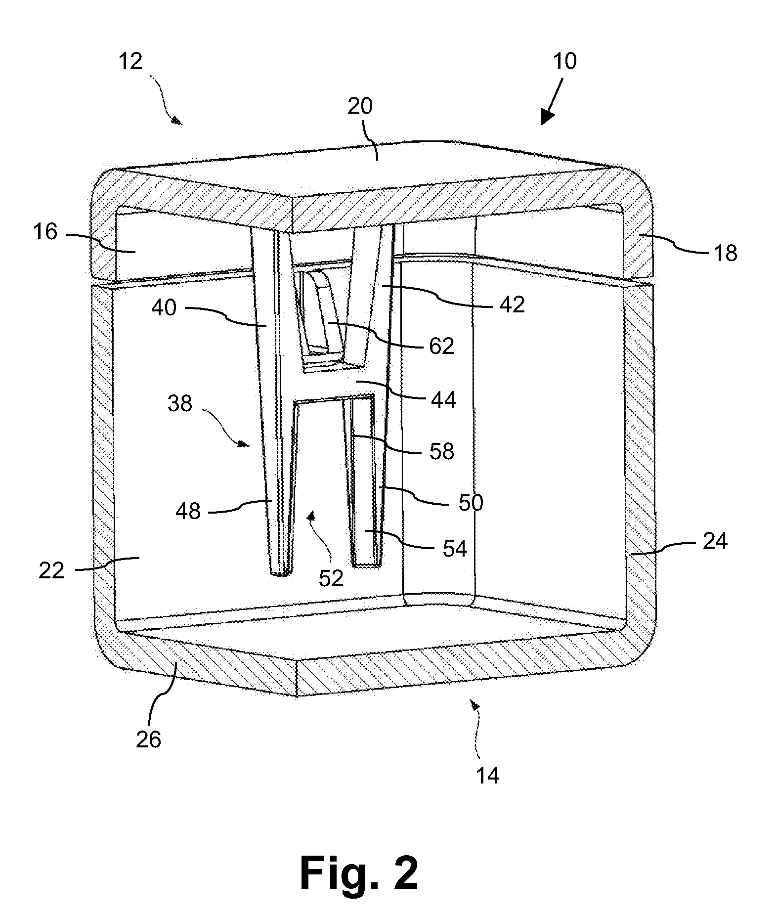
[0028]The housing 10 shown in FIG. 1 comprises an upper housing part 12 and a lower housing part 14 to be joined together by means of a locking structure, as will be explained in the following. While the lower housing part 14 may contain electrical equipment or the like, which shall be protected against the environment, the upper housing part 12 may have the function of a lid which is detachable from the lower housing part 14 by unlocking the locking structure. FIG. 1 shows the upper housing part 12 and the lower housing part 14 in the disengaged state in which the housing 10 is opened. In the following FIGS. 2 and 3, the housing 10 is shown in the closed state wherein the locking structure is engaged so that opening the housing 10 accidentally is impossible or at least unlikely.

[0029]The upper housing part 12 comprises a vertical first sidewall 16, an adjacent vertical second sidewall 18 and a ceiling portion 20. In a similar way, the lower housing part 14 comprises a vertical firs...


PUM


Abstract

The present invention refers to a housing with a locking structure to connect a first housing part (12) with a second housing part (14). The locking structure comprises a flexible snap member (38) extending from the first housing part over an inner wall portion of the second housing part and is provided with a first engaging portion (44). The inner wall portion of the second housing part is provided with a second engaging portion (60). The first and second engaging portions forming a snap fit connection to be released by lifting said snap member from the inner wall portion. A release tool (70) is arranged on or above the bottom of said second housing part to be slidable towards the snap member. The snap member is further provided with a receiving portion being formed to catch the tip (76) of said release tool in a locked manner when the release tool is pushed into the receiving portion.

Description

FIELD OF THE INVENTION[0001]The present invention relates to a housing with a locking structure to interlock different parts of the housing with each other.BACKGROUND OF THE INVENTION[0002]Housings of technical devices exist in a large variety of different embodiments. For example, housings of electrical devices like measurement systems or medical devices serve to protect the damageable electrical parts of the device stored inside the housing. To provide a reliable connection between its different housing parts, the housing is provided with a locking structure which may be released so that the inner parts of the housing are accessible. The locking structure should prevent the different housing parts from falling apart. However, releasing the locking structure should be possible at least for experienced personnel without unnecessary complications. For example, the locking structure can comprise screws or the like which can easily be removed with a corresponding tool like a screwdrive...

Claims


Application Information

Patent Timeline
Patent Type & Authority Applications(United States)
IPC IPC(8): H05K5/02A47B96/00
CPCE05C19/06H05K5/0013F16B5/0664F16B5/0008
Inventor GERST, KALJOPA
Owner KONINKLIJKE PHILIPS ELECTRONICS NV
Why Eureka
Try Eureka