Device for the treatment of biological fluid

a biological fluid and device technology, applied in the field of biological fluid devices, can solve the problems of increased renal insufficiency, large volume of fluid resuscitation, lung failure, etc., and achieve the effect of improving adhesion and prolonging durability

Active Publication Date: 2012-07-26
NOVALUNG
View PDF3 Cites 27 Cited by
  • Summary
  • Abstract
  • Description
  • Claims
  • Application Information

AI Technical Summary

Benefits of technology

[0012]In a preferred embodiment of the invention, the second chamber is located in or within the first chamber, i.e. the second chamber is substantially surrounded by the first chamber. Similarly, the third chamber is preferably located in or within the first chamber, such that the third chamber is also substantially surrounded by the first chamber. By arranging the second and third chambers within and substantially surrounded by the first chamber, the separating surface between the respective chambers can be maximized Thus, the entire surrounding surface of the respective chambers formed by the membrane can serve for the transfer or passage of molecules or components between the biological fluid contained in the first chamber and the second and third chambers.
[0013]If the second and third chambers are disposed within the first chamber, the biological fluid flows on the outside of the second and third chambers and around them. As a result, the dimensions of the first chamber can be made relatively large so that the biological fluid has not to be pressed over long distances through a narrow gap or channel. By that means, high pressure drops in the first chamber can be avoided. Furthermore, when the first chamber is intended and suitable for the biological fluid flow in a direction transversely to the second and third chamber, the second and third chambers within the first chamber can act as a static mixer, which may result in an improved exchange or transfer between the biological fluid and the second and third chambers.
[0027]In a further embodiment of the invention, in particular for the use of the device for treating a biological fluid in medicine, at least one of the membranes, preferably the at least one gas-permeable and liquid-impermeable membrane, and more preferably each of the membranes, can be populated with cells, preferably epithelial cells. For a long-term applicable inventive gas transfer device in the medical context (for example as a lung support system), the colonization of the membrane with cells provides for a significant extension of durability, because a non-specific accumulation of substances from the used media on the membrane is prevented or strongly inhibited, and consequently the membrane is not or only slightly deteriorated in its gas permeability over time. In a preferred embodiment of the invention, at least one of the membranes, preferably the at least one gas-permeable and liquid-impermeable membrane, and more preferably all of the membranes (i.e. also the at least one liquid-permeable membrane) are coated with one or more substances selected from the group consisting of (poly)-saccharide, preferably heparin, nucleic acid, protein, preferably albumin

Problems solved by technology

Patients who must be treated with artificial lung-assist procedure often also suffer from additional renal insufficiency.
Diseases that can lead to lung failure, may require large volumes of fluid resuscitation, and patients often receive significant amounts of blood products.
The resulting physical overload with fluids may possibly lead to a general deterioration of the patient's condition, to pulmonary oedema or even complete organ failure.
This leads however to a complicated constellation of treatment devices and greater stress on the vascular system of the patient.

Method used


Image

  • Device for the treatment of biological fluid
  • Device for the treatment of biological fluid
  • Device for the treatment of biological fluid

Examples


Embodiment Construction

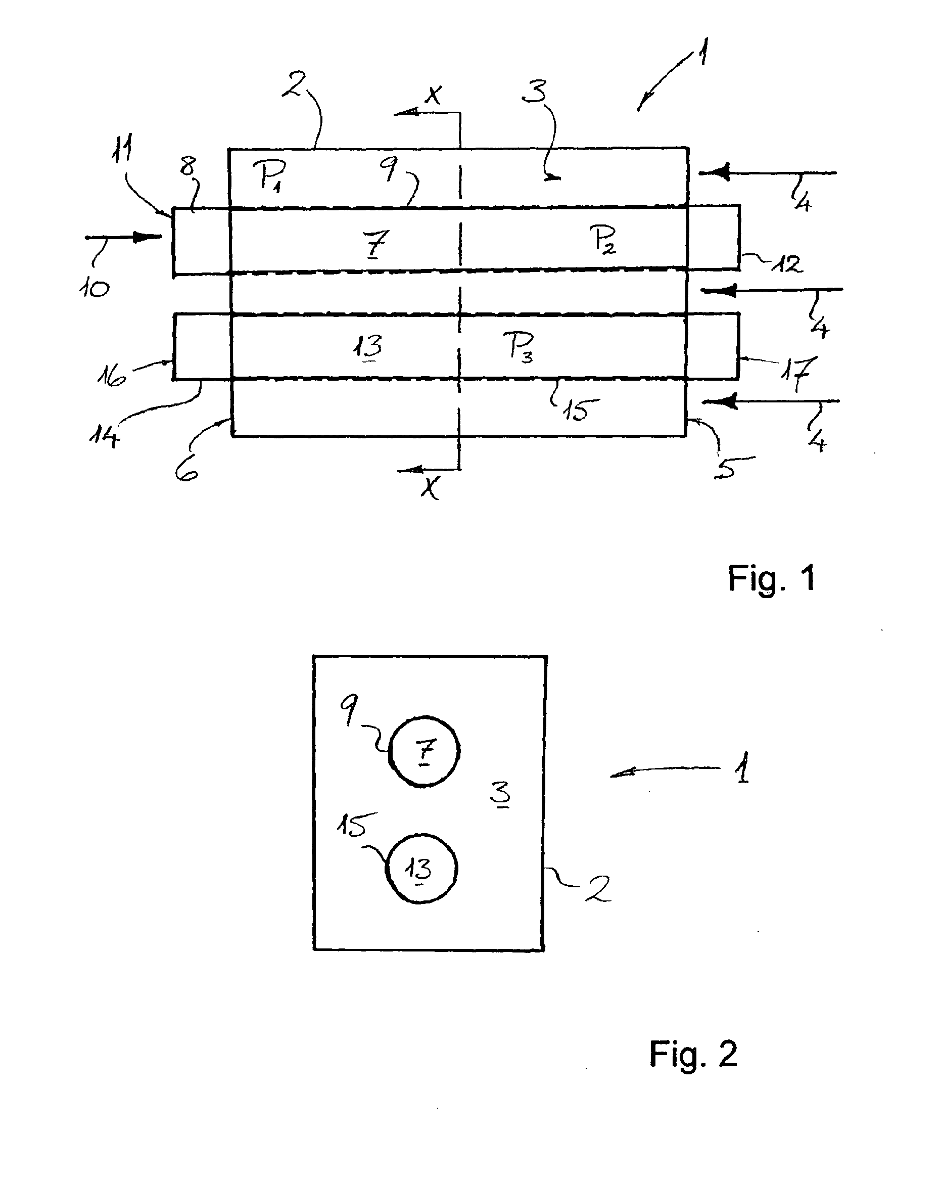
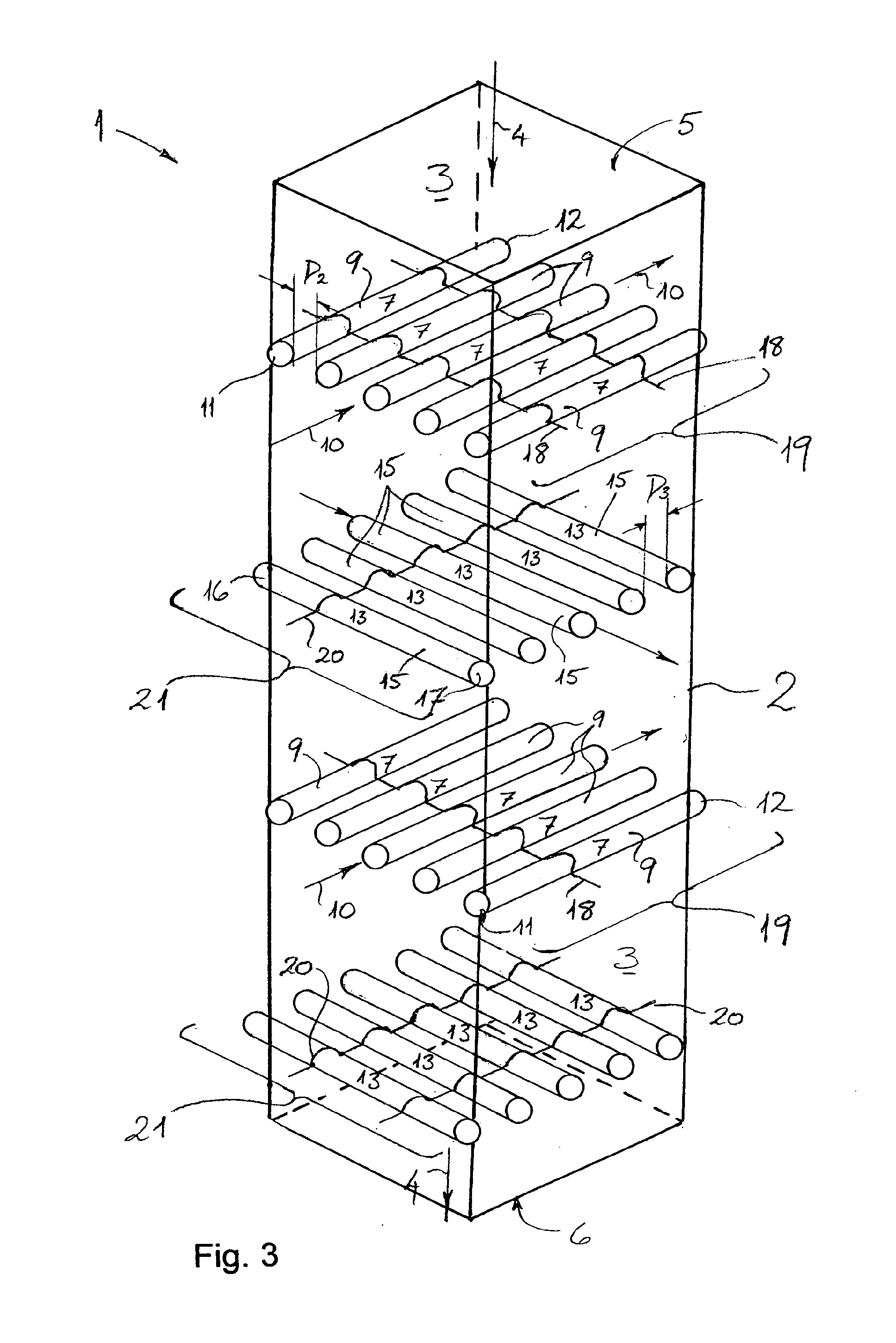
[0043]In FIGS. 1 and 2 a simple representative example of the inventive concept is shown. A device 1 according to the invention includes a housing 2 which encloses or partially defines a first chamber 3. The first chamber 3 is suitable for receiving a biological fluid (as e.g. blood) and is designed as a flow chamber. The biological fluid or blood flows in the direction indicated by the arrows 4 through an inlet 5 in the housing 2 into the first chamber 3 and leaves the first chamber 3 through an opposite outlet 6. The housing 2 is preferably made of a plastic, which does not chemically react with the biological fluid, such as polyethylene or polyurethane.

[0044]Furthermore, the device 1 has a tubular second chamber 7 which extends throughout the first chamber 3 and is substantially surrounded by the first chamber 3. A tubular wall 8 enclosing the cavity of the second chamber 7 is relatively thin and is preferably made of a plastic. The wall 8 serves as a support material for an oute...


PUM

PropertyMeasurementUnit
thicknessaaaaaaaaaa
diameteraaaaaaaaaa
thicknessaaaaaaaaaa

Abstract

The invention relates to a device (1) for the treatment of a biological fluid, comprising at least three chambers, wherein a first chamber (3), which is provided for receiving the biological fluid, and a second chamber (7), which is provided for receiving a gas, are separated from each other by at least one gas-permeable and liquid-impermeable membrane (9), said membrane (9) being used to transfer gas molecules between the first and second chambers (3, 7), and wherein the first chamber (3) and a third chamber (13) are separated from each other by at least one liquid-permeable membrane (15) which is used to transfer one or more components between the first and third chambers (3, 13). The second chamber (7) is delimited or enclosed by the at least one gas-permeable and liquid-impermeable membrane (9) and is located inside the first chamber (3) or is substantially enclosed by the first chamber (3) such that the biological fluid surrounds the second chamber (7). Similarly, the third chamber (13) is delimited or enclosed by the at least one liquid-permeable membrane (15) and is located inside the first chamber (3) or is substantially enclosed by the first chamber (3) such that the biological fluid surrounds the third chamber (13).

Description

BACKGROUND OF THE INVENTION[0001]The invention relates to a device for the treatment of a biological fluid, particularly a device comprising a chamber which is suitable for receiving a biological fluid, and another chamber which is suitable for receiving a gas, wherein the chambers are separated from each other by a gas-permeable membrane, and wherein the membrane allows a transfer of gas molecules between the chambers.[0002]It is a gassing or degassing device, in which one or more gases can pass from one medium into another, or a gas exchange device, which allows the exchange of one or more gases between two media. Such devices are used in the fields of chemistry, biotechnology and medicine. An important application in medicine is the enrichment of blood with oxygen and / or the removal of carbon dioxide from blood. Such measures are e.g. essential for surgery of various characters and in the treatment of various pulmonary diseases.[0003]Currently, the only long term effective treatm...

Claims


Application Information

Patent Timeline
Patent Type & Authority Applications(United States)
IPC IPC(8): C12M1/00A61M1/00
CPCA61M1/16A61M1/1698A61M1/34B01D63/043B01D2317/08B01D2319/06B01D63/026A61M1/3403A61M2205/3334A61M2205/3331
Inventor MAURER, ANDREAS
Owner NOVALUNG
Why Eureka
Try Eureka