Frequency determining circuit and semiconductor device

Inactive Publication Date: 2012-07-26
HITACHI LTD
View PDF7 Cites 5 Cited by
  • Summary
  • Abstract
  • Description
  • Claims
  • Application Information

AI Technical Summary

Benefits of technology

[0005]In a conventional technique of determining the frequency including the technique of Patent Document 1 as described above and others, when the frequency is specified from different data signals having a plurality of frequencies, it is difficult to determine the frequency even if a pulse number of each data signal is counted. This is because

Problems solved by technology

In a conventional technique of determining the frequency including the technique of Patent Document 1 as described above and others, when the frequency is specifi

Method used


Image

  • Frequency determining circuit and semiconductor device
  • Frequency determining circuit and semiconductor device
  • Frequency determining circuit and semiconductor device

Examples


Example

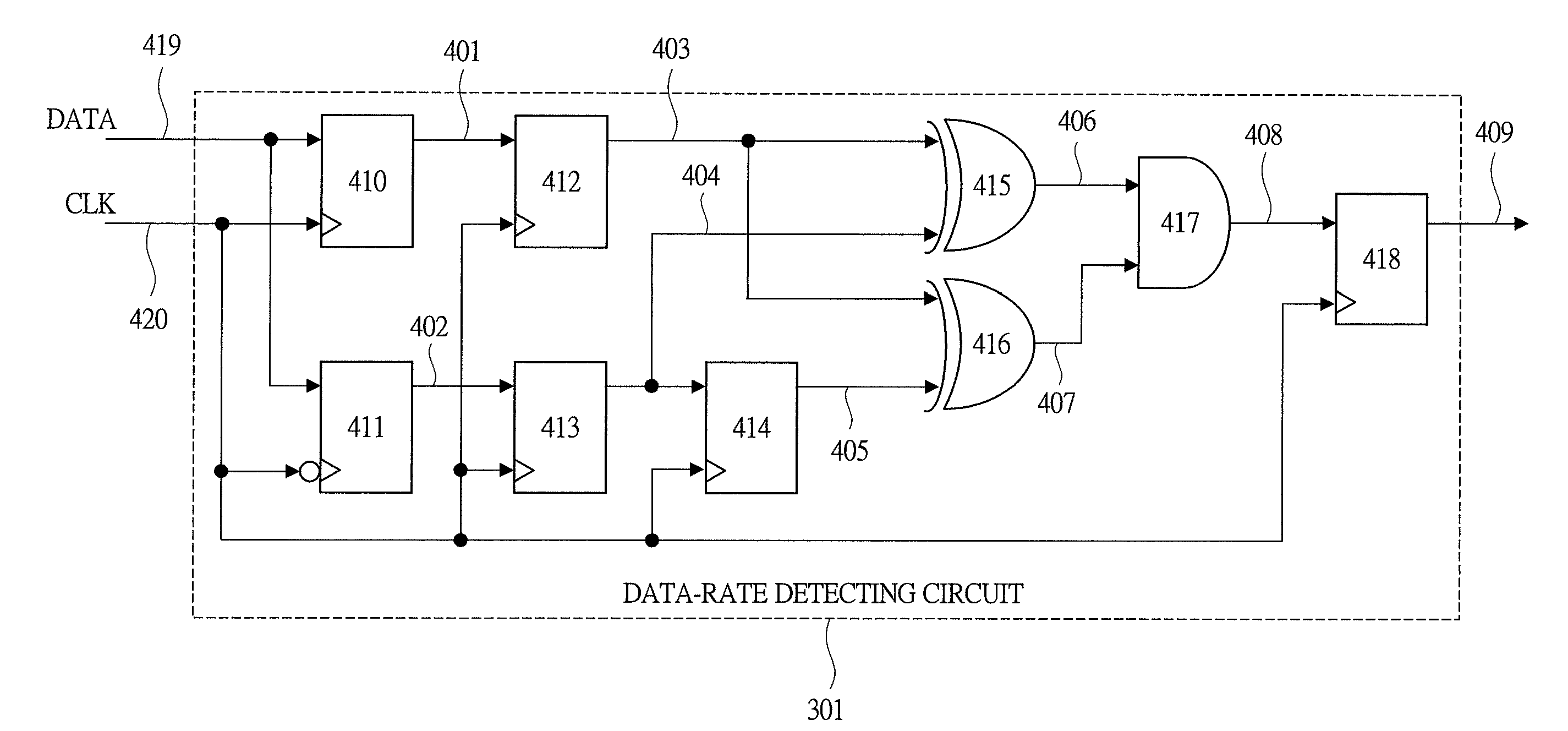
[0034]A first embodiment of the present invention is explained with reference to FIGS. 1 to 7.

[0035]

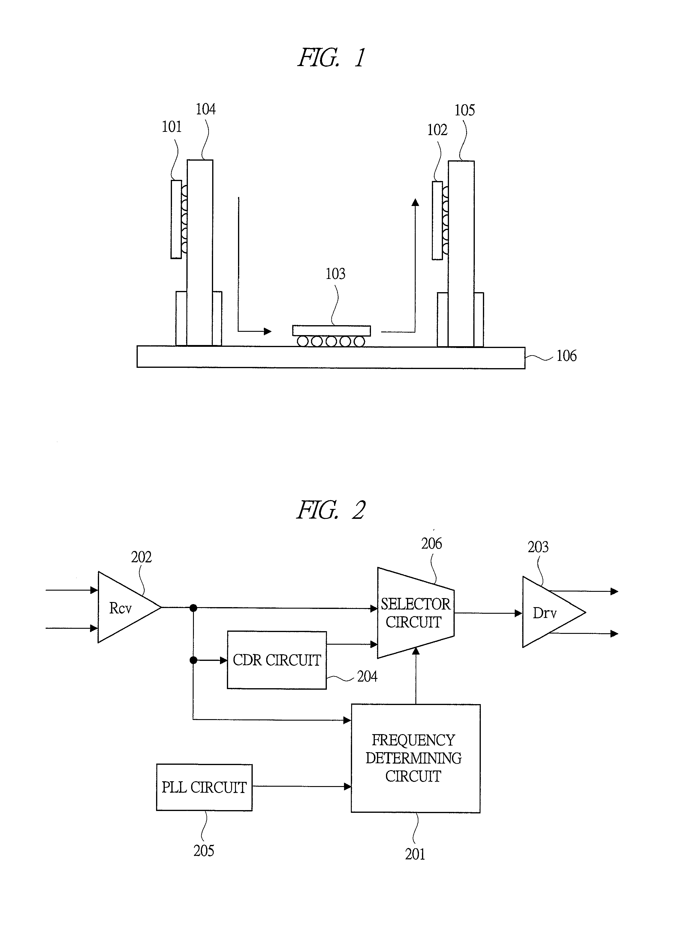
[0036]First, with reference to FIG. 1, one configuration example of a data-transfer system including a plurality of integrated circuits (semiconductor devices) according to a first embodiment, which perform data transfer, is explained. FIG. 1 is a diagram showing one configuration example of this data-transfer system including the plurality of integrated circuits performing the data transfer.

[0037]The data-transfer system shown in FIG. 1 includes: a transmitting-side integrated circuit 101; a board 104 on which this integrated circuit 101 is mounted; a receiving-side integrated circuit 102; a board 105 on which this integrated circuit 102 is mounted; a data-transfer integrated circuit 103; and a motherboard 106 on which this integrated circuit 103 is mounted. The board 104 on which the transmitting-side integrated circuit 101 is mounted and the board 105 on which the receiving-side in...

Example

[0071]A second embodiment of the present invention is explained with reference to FIGS. 8 to 11.

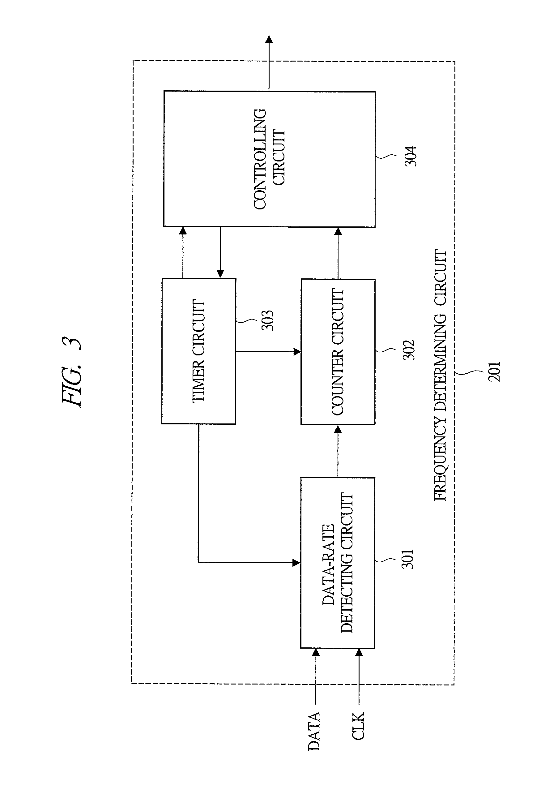
[0072]In the present second embodiment, the configuration (FIG. 1) of the data-transfer system including the plurality of integrated circuits performing the data transfer, the configuration (FIG. 2) of the transmission mechanism performing the data transfer of the data-transfer integrated circuit included in this data-transfer system, and the configuration (FIG. 3) of the frequency determining circuit configuring the transmission mechanism performing the data transfer of this data-transfer integrated circuit are the same as those in the above-described first embodiment, and therefore, their descriptions are omitted here.

[0073]The present second embodiment is different from the above-described first embodiment (FIG. 4) in the configuration and the operation of the part of the data-rate detecting circuit configuring the frequency determining circuit, and a different point of the part of the...

Example

Modification Example of Second Embodiment (or First Embodiment)

[0081]FIG. 11 is a circuit diagram showing an example that the part of the data-rate detecting circuit 301 is configured by two stages of the data-rate detecting circuits 301 with the delay circuit 821 as a modification example of the second embodiment (or the first embodiment).

[0082]In the part of the data-rate detecting circuit 301 shown in FIG. 11, the data-rate detecting circuit 301 (on an upper side in FIG. 11) which directly receives the data signal (DATA) and the data-rate detecting circuit 301 (on a lower side in FIG. 11) which receives the signal obtained after the delay via the delay circuit 821 are combined to be connected in parallel so as to detect each pulse, so that the pulse width shorter than the predetermined pulse width can be detected regardless of the pattern. Therefore, in this modification example of the second embodiment (or first embodiment), the frequency of the data signal further having the m...


PUM


Abstract

A technique capable of determining a frequency of a data signal having a mixture of short and long pulse widths is provided. In a frequency determining circuit for determining a frequency from different data signals having a plurality of frequencies, the frequency determining circuit includes a circuit which acquires the different data signals having the plurality of frequencies and determines the frequency based on the number of counts of the signal having the pulse width shorter than the predetermined pulse width. For example, the signal having the pulse width shorter than the predetermined pulse width is detected, and the number of pulses of the detected signal is counted. By previously making correspondence of the frequency with the number of counts of the pulse, the frequency can be determined based on the number of counts.

Description

CROSS-REFERENCE TO RELATED APPLICATION[0001]The present application claims priority from Japanese Patent Application No. 2011-012743 filed on Jan. 25, 2011, the content of which is hereby incorporated by reference into this application.TECHNICAL FIELD OF THE INVENTION[0002]The present invention relates to a technique of a frequency determining circuit. More particularly, the present invention relates to a technique effectively applied to a frequency determining circuit for determining a frequency from a plurality of data signals having different frequencies and to a semiconductor device including this frequency determining circuit.BACKGROUND OF THE INVENTION[0003]For example, a data rate for transferring data between transmitting / receiving LSIs has increased as increase in a speed of an IT device in recent years, and deterioration of the transmitted signal has occurred due to a transmission channel. Therefore, the long-distance high-speed transmission has been difficult. Against suc...

Claims


Application Information

Patent Timeline
IPC IPC(8): G06F19/00G01R23/10
CPCG01R23/155
Inventor SATOU, HIRONORIISEZAKI, TAKESHIHOKARI, TOMOFUMI
Owner HITACHI LTD
Why Eureka
Try Eureka