Coolant supply device and supply method

a technology of supply device and coolant, which is applied in the direction of fluid pressure control, positive displacement liquid engine, instruments, etc., can solve the problems of complicated control system and complex control system

Active Publication Date: 2014-09-25
NIPPON OIL PUMP
View PDF2 Cites 2 Cited by
  • Summary
  • Abstract
  • Description
  • Claims
  • Application Information

AI Technical Summary

Benefits of technology

[0017]According to the present invention provided with the structure described above, since the pump discharge pressure is controlled (for example, the rotation rate of the pump 101 or the rotation rate of the electric motor 1 is increased or decreased) by comparing the target value (the target pressure) with the measured pump discharge pressure, only the discharge pressure of the pump (101) is a control parameter, and there is no need to perform feedback control of the rotation rate of the pump (101) (or the electric motor 1).
[0018]That is, according to the present invention, there is no need to perform complicated rotation rate feedback control of the pump (101) (or the electric motor 1), and it is possible to supply a coolant appropriately to the tool (D) by controlling only the discharge pressure of the pump (101).
[0019]Moreover, according to the present invention, it is possible to determine the coolant flow path diameter of the tool (D) and an optimum pump discharge pressure (target pressure) for the coolant flow path diameter independently on the pump (101) side without inputting, to the pump (101) side, information from the tool (D) such as a center-through coolant drill, for example, information on a coolant flow path diameter in the set tool (D).
[0020]As is obvious to the skilled in the art, it is very difficult to determine, on the pump (101) side, a target pressure automatically in response to a coolant flow path diameter when the coolant flow path diameter of the tool (D) such as a center-through coolant drill is determined. This is because there are an infinite number of combinations of the tool (D) and the pump (101) and the coolant flow path diameter of the tool (D) also varies widely.
[0021]On the other hand, according to the present invention, it is possible to determine the coolant flow path diameter of the tool (D) and the target pressure independently on the pump (101) side without inputting, to the pump (101) side, information on the coolant flow path diameter of the tool (D) such as a center-through coolant drill.
[0022]As a result, even when there are an infinite number of combinations of the tool (D) and the pump (101) and the coolant hole diameter of the tool (D) varies widely, it is possible to determine a coolant hole diameter of the tool (D) on the pump side that supplies a coolant, determine an optimum coolant discharge pressure for the coolant hole diameter, and perform boring by the tool (D) appropriately.

Problems solved by technology

However, in the control by which so-called constant-horsepower operation that makes the product of the pressure and the flow rate of a coolant nearly constant is performed, since there are two types of parameters to be controlled: a pressure and a flow rate, the control itself becomes complicated, which complicates a control system.

Method used


Image

  • Coolant supply device and supply method
  • Coolant supply device and supply method
  • Coolant supply device and supply method

Examples


Embodiment Construction

[0032]Hereinafter, with reference to the attached drawings, an embodiment of the present invention will be described.

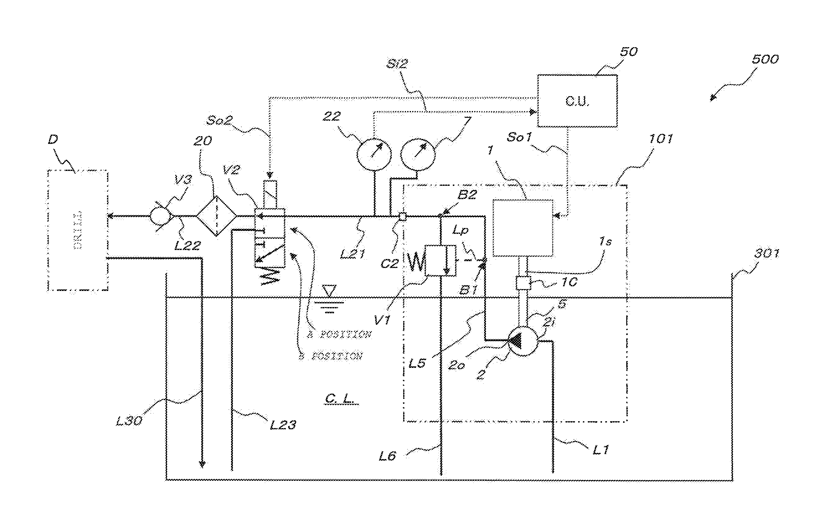
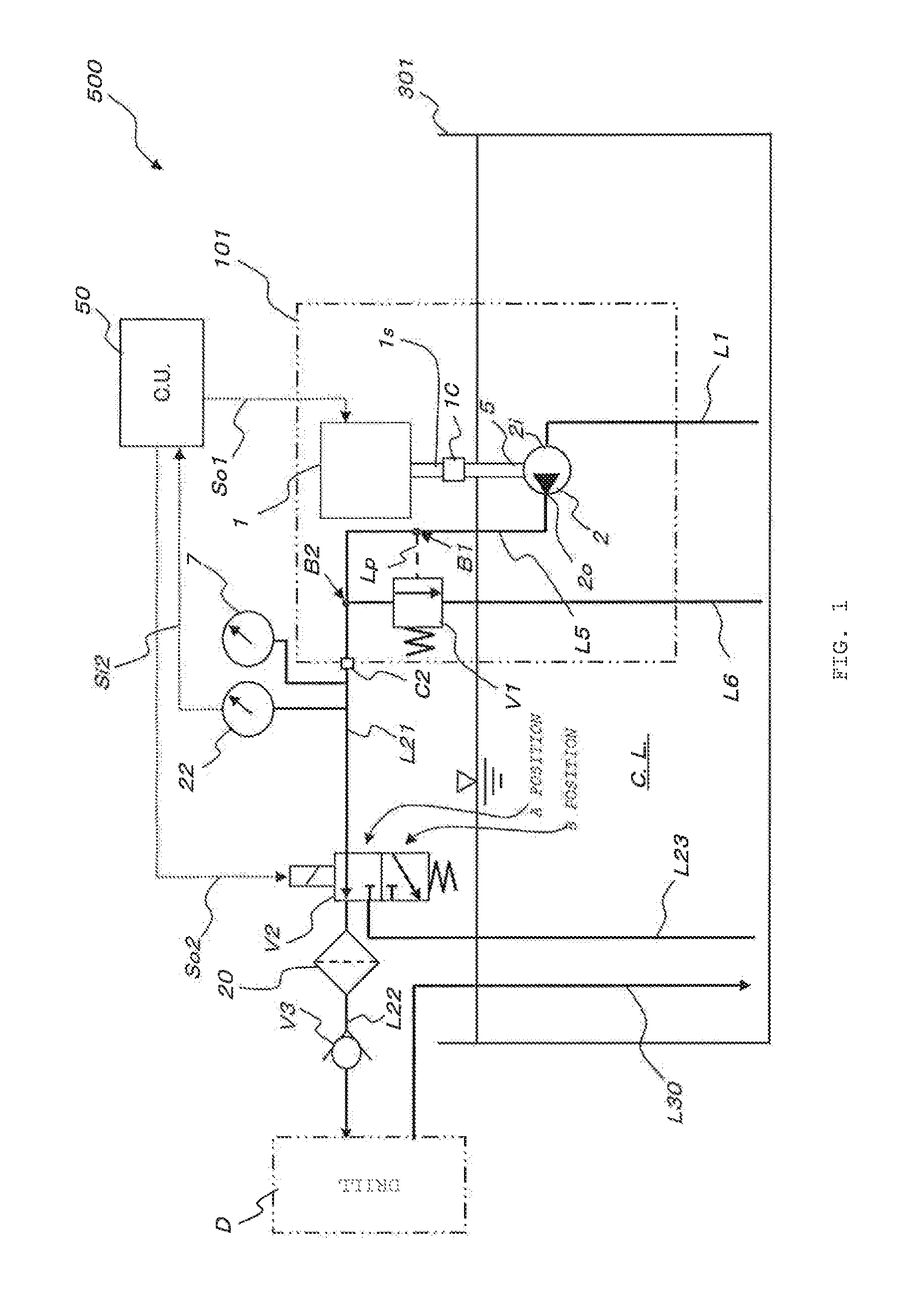
[0033]In FIG. 1, the whole of a coolant supply device according to the embodiment of the present invention is identified with a numeral 500.

[0034]In addition, the coolant supply device 500 includes a pump for a coolant (for example, a gear pump) 101, a flow path change-over valve V2 (of the 3-port 2-position type, for example), a coolant storage tank 301, and a control device 50.

[0035]The pump 101 for a coolant includes an electric motor (for example, a brushless motor) 1, a high pressure generating section (a high-pressure pump) 2, and a safety valve V1.

[0036]In the pump 101 for a coolant shown in FIG. 1, the high pressure generating section 2 is driven and rotated by a pump drive shaft 5. The pump drive shaft 5 is connected to a rotating shaft 1s of the electric motor 1 by a coupling 1C.

[0037]Though not shown in the drawing, it is also possible to omit the pump driv...


PUM


Abstract

The purpose of the invention is to provide a coolant supply device and supply method that can appropriately control the spraying of coolant using a single parameter.
To that end, the invention is provided with a pump (101) that supplies coolant to a tool (D), a measurement device (22) that measures the discharge pressure of the pump (101), and a control device (50). The control device (50) has a function for determining, from the rotation rate of the pump (101), the coolant flow path diameter for the tool (D) and the target value for the pump discharge pressure (target pressure) when the tool (D) is drilling.

Description

TECHNICAL FIELD[0001]The present invention relates to a technique of supplying a coolant to a machine tool, in particular, a cutting tool with an oil hole such as a drill of the center-through (spindle-through) coolant type.BACKGROUND ART[0002]In a machining center of the center-through (spindle-through) coolant type shown in FIG. 9, a machining center 200 includes a processing table 205, a main shaft 210, a tool 220, and a coolant nozzle 240. To the processing table 205, a work 400 which is an objected to be worked on is fixed. A coolant pump 100 shown in FIG. 9 is the type of pump that discharges a low-pressure coolant and a high-pressure coolant from one pump.[0003]A high-pressure line Lh of the coolant pump 100 communicates with the tool 220, and a low-pressure line Ll of the coolant pump 100 communicates with the coolant nozzle 240.[0004]The coolant pump 100 is attached to a coolant storage tank 300.[0005]In the machining center 200 shown in FIG. 9, the low-pressure coolant dis...

Claims


Application Information

Patent Timeline
Patent Type & Authority Applications(United States)
IPC IPC(8): B23Q11/12
CPCB23Q11/126B23Q11/1038F04B49/065F04C14/08F04C2/10F04B2205/05F04B2203/0209F04C2270/18B23Q11/1015G05D16/024B23B47/00B23Q11/00B23Q11/10F04B49/00F04B49/06G05D7/00G05D7/06G05D16/20
Inventor KAWANO, YUJI
Owner NIPPON OIL PUMP
Why Eureka
Try Eureka