Adjustable furniture

a technology of adjustable furniture and furniture, applied in the direction of chairs, sofas, transportation and packaging, etc., can solve the problems of affecting the stiffness or resistance to movement of moving parts, heavy and costly, and often mechanically complex support arrangements, etc., and achieves significant mechanical advantages

Active Publication Date: 2012-08-02
DEWERTOKIN TECHNOLOGY GROUP CO LTD
View PDF28 Cites 55 Cited by
  • Summary
  • Abstract
  • Description
  • Claims
  • Application Information

AI Technical Summary

Benefits of technology

[0012]Preferably the back support provides at least part of a lever arrangement, movement of which lever arrangement also moves the intermediate member with respect to the base. In this way significant mechanical advantage may be achieved by utilising the back support of the item of furniture for example the backrest in a chair, as a lever to move the intermediate member with respect to the base, for example, in a forward linear direction in the case of a zero-wall chair. In this way the weight of the seated user's upper body can be distributed to actuate the lever to pivot the back support and thereby move the intermediate support forward. The back rest of an adjustable bed may be used in much the same way, typically by moving the backrest using an electrical actuator which will move the intermediate support with respect to the base to provide “zero-wall” functionality.
[0013]In preferred embodiments the second guide means provides a fulcrum about which the lever arrangement acts to move the intermediate member with respect to the base. In this way the fixed part of the second guide means defines a fulcrum point for providing the mechanical advantage (leverage) to move the intermediate support with respect to the base.

Problems solved by technology

Such support arrangements are often mechanically complex, heavy and costly making transportation, handling and use awkward.
These considerations place severe restrictions on furniture design.
The complex series of linkages and connections in known support arrangements often results in manufacturing variations, due to tolerances etc, which affects the stiffness or resistance to movement of the moving parts.
This is a particular disadvantage in the case of manually operated furniture where identical items of furniture may require different degrees of effort to be applied by the user to adjust the furniture.

Method used


Image

  • Adjustable furniture
  • Adjustable furniture
  • Adjustable furniture

Examples


second embodiment

[0096]Referring now to FIG. 14 which shows part of a recliner chair arrangement according to the invention. The view of FIG. 14 is similar to that of FIG. 5 in that it shows one side of a support and operating mechanism for a recliner chair, sofa or the like. The general principle of construction and operation of the arrangement shown in FIG. 14 is substantially the same as that in the previous embodiment in that there is provided a base support 16 an intermediate support 18 and a back support 20. In this embodiment the L-section chassis legs 22 are replaced by a planar support panel 110 having a sphinx-shape profile which, on the other side of the panel to that shown in the drawing of FIG. 14 carries three roller bearings at three positions indicated 112, 114 and 116 in the drawing. The roller bearing 118 rotatably mounted on the other side of the panel at 116 is equivalent to the bearing 48 in the previous embodiment but instead of engaging the upper lip of the guide 76 the bearin...

first embodiment

[0098]The side panel 124 differs slightly from the side panel 12 of the first embodiment in that it includes an upstanding portion 134 at the rear of the panel which includes a radial slot 136 which accommodates a pair of roller bearings 138, 140 rotatably mounted on the side of the back support arm 122. The back support arm 122 is therefore rotatable relative to the intermediate support panel 124 about an axis coincident with the centre of curvature of the slot 136.

[0099]The support and operating arrangement of the second embodiment of the present invention is particularly suitable for manufacture from board material such as MDF or similar high strength low cost material. The base support member 110 is preferably manufactured from such a board by CNC machining the profile, followed by attachment of the roller bearings at the appropriate locations. Similarly the planar side panel 124 is preferably also manufactured by CNC machining to include the guide slots etc. The back support ar...

third embodiment

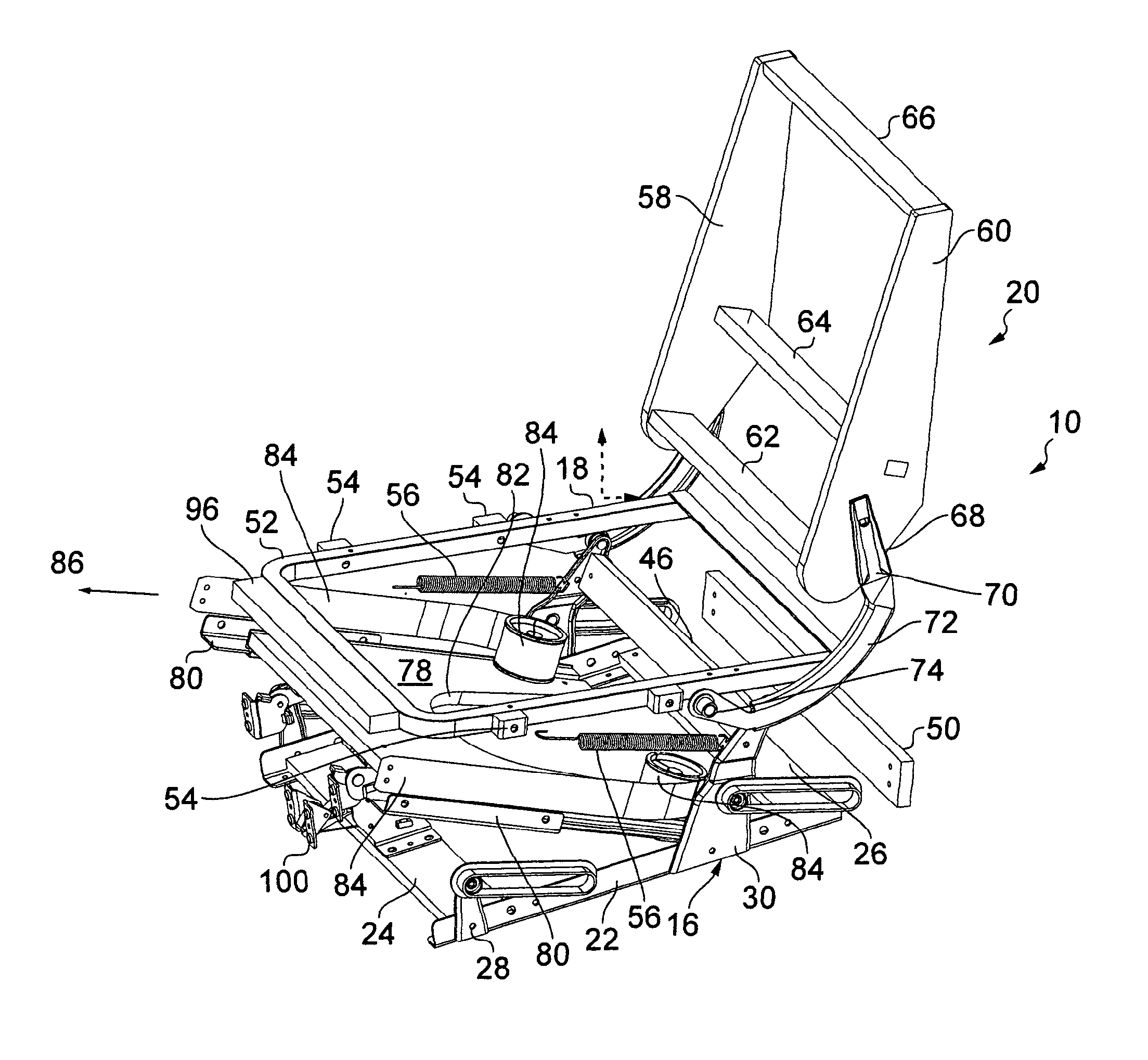
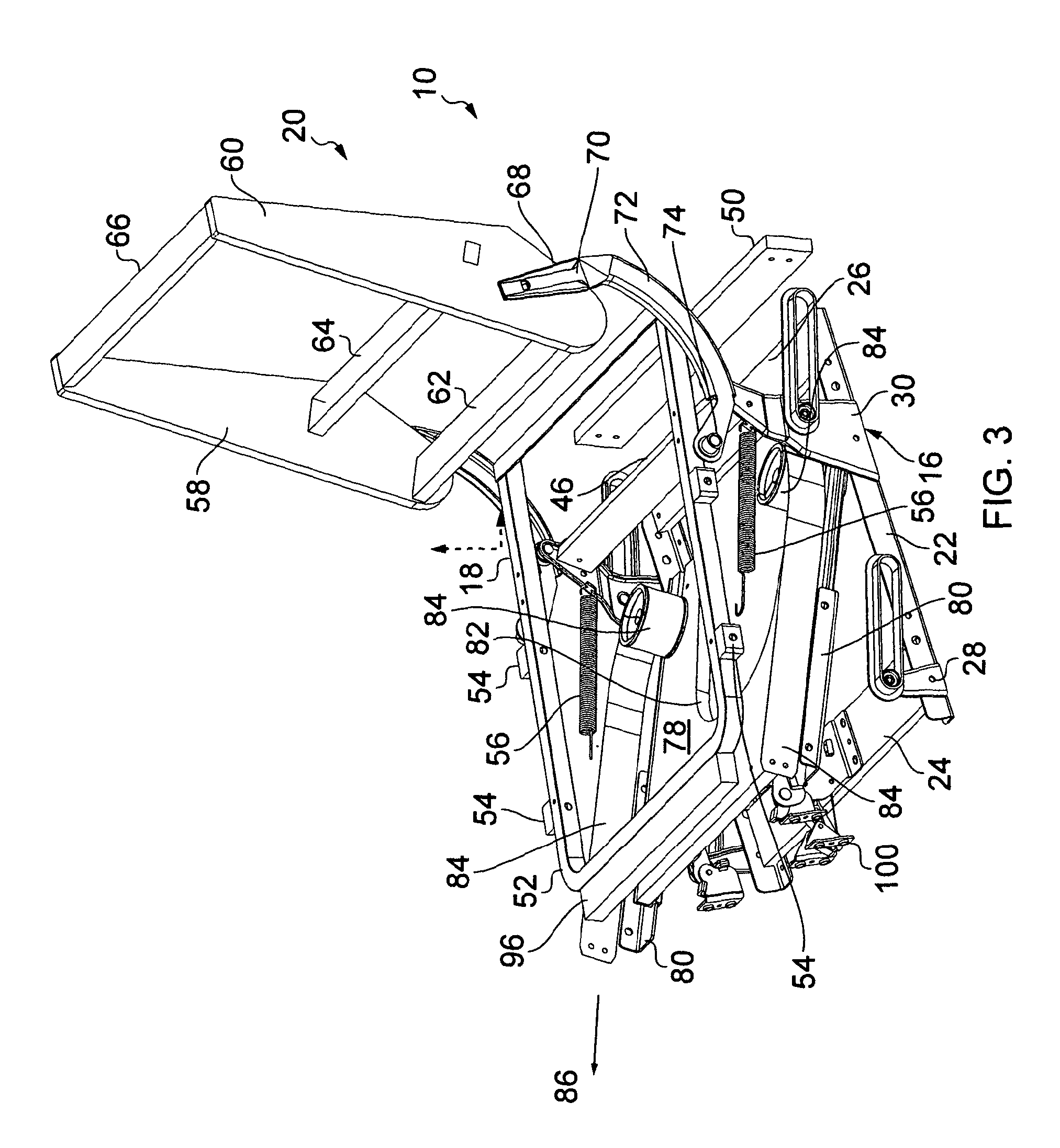
[0105]FIG. 18 is a perspective view from the rear and above of a support and operating mechanism 10 according to the present invention. FIG. 19 is a perspective view from the rear of the support and operating mechanism of FIG. 18 with the left hand side panel and footrest panel omitted for clarity. The recliner part of the support and operating mechanism of FIGS. 18 to 21 is substantially identical to that described above with reference to the embodiment of FIGS. 3 to 13. The footrest part of the support and operating mechanism is different. As can be seen in the drawing of FIG. 18 The footrest board or panel is pivotally connected to a pair of elongate arcuate mounting arms provided on both lateral sides of the chair. The panel 14 is pivotally connected to the arms 140 at a point substantially midway between the top and bottom edges 92, 94 with the pivotal connections between the arms 140 and the panel 14 provided in the plane of the panel 14 in respective apertures 142. In this wa...


PUM


Abstract

An adjustable furniture such as a recliner chair or adjustable bed comprising a base, an intermediate support and a back support. Both the intermediate support and the back support are guided for movement relative to the base by a second guide means while the base moves along a first guide means. The first guide means include at least one guide associated with one of the base and intermediate support and at least one follower associated with the other of the base and intermediate support. The second guide means includes at least one guide associated with one of the base support and the back support and at least one follower associated with the other of the base support and the back support.

Description

CROSS REFERENCE TO RELATED APPLICATIONS[0001]This application relates to and claims priority from PCT / GB2010 / 001565 filed on Aug. 18, 2010, the entire contents of which are incorporated herein by reference, which in turn claims the priorities of the GB Application GB 0914436.1 filed on Aug. 18, 2009 and the GB Application GB 0918685.9 filed on Oct. 23, 2009.FIGURE SELECTED FOR PUBLICATION[0002]FIG. 5BACKGROUND OF THE INVENTION[0003]1. Field of the Invention[0004]This invention relates to adjustable furniture, for example chairs, beds or the like in which the position of one part of the furniture can be moved relative to another. The adjustment may be powered using electrical motors or the like or manual.[0005]2. Description of the Related Art[0006]Adjustable chairs are known in which the angle of the backrest can be changed in order to provide a recline position and / or in which a moveable footrest can be moved forwards and outward. Recliner chairs of this type are available in which...

Claims


Application Information

Patent Timeline
Patent Type & Authority Applications(United States)
IPC IPC(8): A47C1/035A61G7/015A47C1/034A47C1/024A47C15/00
CPCA47C1/03294A47C1/035A47C20/08A47C7/50A47C7/54A47C1/032A47C1/034A47C17/17A47C17/175A47C20/04A47C1/031
Inventor ROBERTSON, DALE
Owner DEWERTOKIN TECHNOLOGY GROUP CO LTD
Why Eureka
Try Eureka