
Pump

a technology of pump and gas chamber, applied in the field of pumps, can solve the problems of destroying accuracy, small amount of air lost minimizing the loss of compressed air from the storage chamber, so as to increase the shooting power, enhance accuracy, and save energy

Inactive Publication Date: 2005-10-25
NIBECKER JR ALFRED F
View PDF28 Cites 5 Cited by
  • Summary
  • Abstract
  • Description
  • Claims
  • Application Information

AI Technical Summary

Benefits of technology

[0011]This invention provides an air gun which stores and imparts increased shooting power without requiring the shooter to be of more than average strength. The gun uses a unique pumping action with a large mechanical advantage to store energy and efficiently transfer stored energy to the pellet to achieve muzzle energy in excess of 40 foot-pounds.
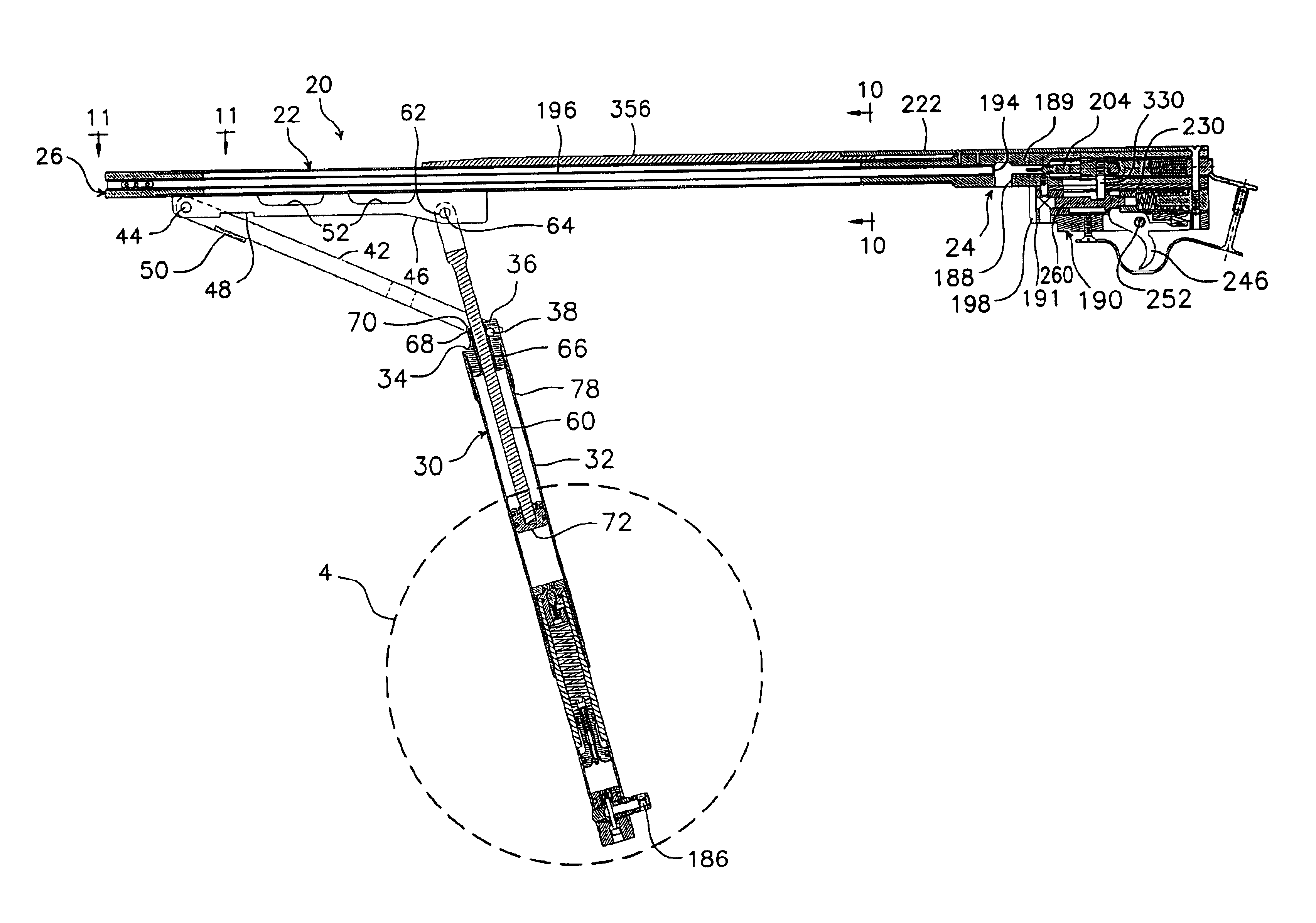
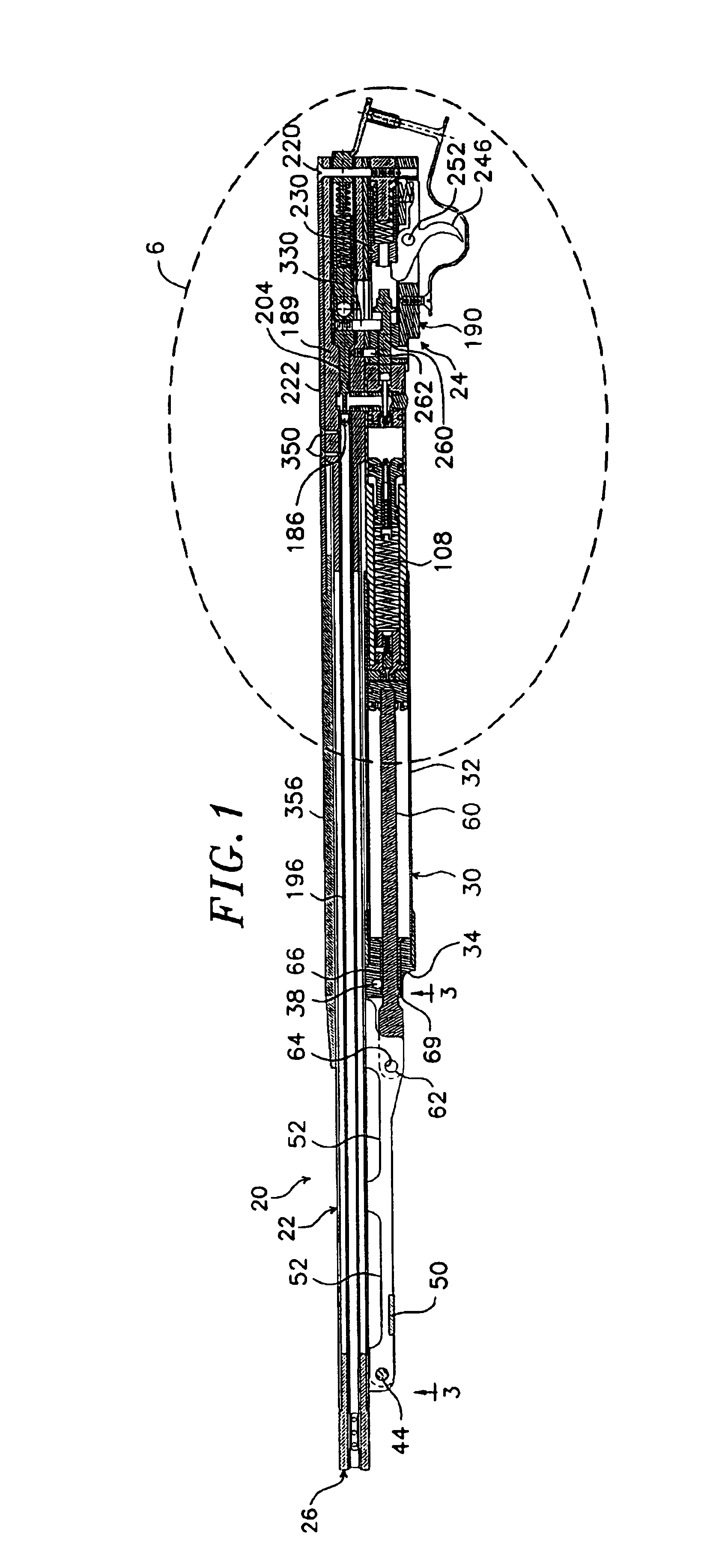
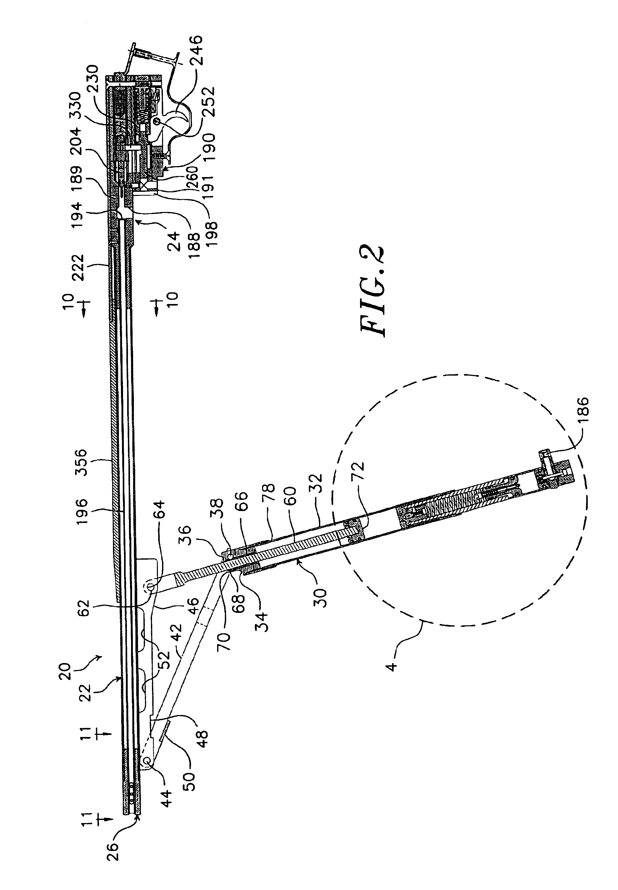
[0012]The air gun of this invention uses an improved air pump which includes a pump cylinder and a pump piston mounted to reciprocate within the cylinder. The pump cylinder and a piston rod connected to the piston are each connected to the barrel of the gun to pivot about separate respective longitudinally spaced axes, which are transverse to the longitudinal axis of the barrel. As the pump cylinder and piston rod are moved back and forth around their respective the pivot points, the cylinder and piston reciprocate relative to each other to pump air into an inlet of a high pressure housing carried by the pump cylinder. A firing conduit connected to the high pressure housing releasably connects an outlet of the high pressure housing to the breech end of a gun barrel when the pump cylinder is moved to be parallel with the barrel. A trigger-responsive firing valve in the firing conduit releases air from the high pressure housing into the breech end of the barrel to fire a pellet from the gun. In a preferred embodiment, the piston rod is secured at one end to the piston, and at the other end to a first pivot point on the gun barrel. An elongated drive link is secured at one end to a pivot point on the cylinder, and at the other end to a second pivot point on the gun barrel, so that as the cylinder and piston are moved back and forth about the first and second pivot points, the piston reciprocates in the cylinder to force air through a check valve and into the high pressure housing. The length of the drive link and the longitudinal spacing between the first and second pivot points are set so when the pump cylinder is moved to be substantially parallel to the barrel, the piston contacts the check valve which admits air into the high pressure housing so a maximum amount of compressed air is transferred to the high pressure housing with each compression stroke of the pump. The first pivot point is located to the rear of the second pivot point and is spaced slightly farther from the longitudinal axis of the gun barrel so when the pump cylinder is moved toward the gun barrel to a “dead center” position, which places the longitudinal axis of the piston rod and piston substantially in alignment with the first and second pivot points, the piston contacts the check valve with maximum force. At this point, the pump cylinder extends rearwardly and away from the gun barrel to leave ample space for gripping the rear end of the cylinder to actuate the pump. Further movement of the pump cylinder toward the gun barrel carries the piston rod and piston slightly past the “dead center” position. The elasticity inherent in the gun and pump components accommodates movement of the pump cylinder back and forth through the “dead center” position, which acts as a moderate detent to hold the pump cylinder snugly against the barrel when the gun is to be prepared for firing.

Problems solved by technology

However, loss of compressed air from the storage chamber is minimized because the flow path for air from the storage chamber to the firing chamber is so restricted, that only a small amount of air is lost from the storage chamber before the pressure relief valve closes.
The gun of this invention supplies such a large mass of high-velocity compressed air behind the pellet as the pellet leaves the barrel, there is a tendency for the air to overrun the pellet and cause it to precess or tumble, which would destroy accuracy.

Method used


Image

  • Pump
  • Pump
  • Pump

Examples


Embodiment Construction

[0039]Referring to FIGS. 1 and 2, an air gun 20 includes an elongated barrel 22 having a breech end 24, and a muzzle end 26. A pump 30 includes an elongated pump cylinder 32 adjacent and parallel to the underside of the gun barrel when the gun is in the firing position shown in FIG. 1. An externally threaded plug 34 threaded into the forward end of the pump cylinder includes a forwardly extending ear 36 (FIG. 4D). A plug pivot pin 38 extends through a transverse bore 40 (FIG. 4C) offset from the longitudinal center line of the plug to secure the plug and forward end of the cylinder between the rear ends of a pair of identical elongated and laterally spaced longitudinally extending drive links 42 (FIG. 3) secured at their forward ends by a transverse pivot pin 44 to the forward end of an elongated and longitudinally extending barrel-stiffening web 46 welded at its upper edge to the underside of the forward end of the gun barrel. A downwardly opening notch 48 (FIG. 2) in the lower edg...


PUM


Abstract

An air gun includes an air pump with a pumping piston mounted to reciprocate within a pump cylinder, which is mounted on the barrel of the gun to pivot about an axis transverse to the longitudinal axis of the barrel so that as the pump cylinder is moved back and forth around the pivot, the cylinder and piston reciprocate relative to each other to pump air into a high pressure housing carried by the pump cylinder. A discharge conduit is also provided for releasably connecting the high pressure housing to the breach end of a gun barrel when the pump is moved toward the barrel. A firing valve in the discharge conduit releases air from the high pressure housing into the breach end of the barrel. Preferably, a floating differential piston disposed to reciprocate in a high pressure housing divides the housing into a storage chamber and a high pressure chamber. A pressure relief valve extending through the differential piston permits compressed air to flow from the storage chamber to the firing chamber, and maintains a higher pressure in the storage chamber than in the firing chamber. The end of the piston in the firing chamber seals a greater cross sectional area than the end of the piston in the storage chamber so that a piston is forced to move into the storage chamber by an amount which balances the forces on the opposite end of the piston. The gun barrel muzzle includes at least one lateral opening for venting compressed air as a pellet leaves the muzzle end of the barrel.

Description

CROSS-REFERENCE TO RELATED APPLICATION(S)[0001]This application is a divisional application of U.S. patent application Ser. No. 10 / 427,637, filed Apr. 30, 2003 now U.S. Pat. No. 6,701,908 which is a divisional application of U.S. patent application Ser. No. 09 / 990,908, filed Nov. 16, 2001, now U.S. Pat. No. 6,581,585, the disclosures of which are incorporated herein by reference.BACKGROUND OF THE INVENTION[0002]This invention relates to pumps which can supply a charge of compressed gas on demand, such as for guns which use a charge of compressed air to fire a pellet.[0003]Air guns have a wide following because laws limiting their use are not as restrictive as for powder guns, and air guns are relatively inexpensive to shoot. Air gun shooting is an Olympic sport, and hunting with an air gun removes much of the danger inherent with powder guns while retaining and enhancing the challenge.[0004]Air guns fall into three major groups:[0005]1. Pump guns: These guns use one or more strokes ...

Claims


Application Information

Patent Timeline
Patent Type & Authority Patents(United States)
IPC IPC(8): F41B11/00F41B11/32F41B11/30
CPCF41B11/683F41B11/723
Inventor NIBECKER, JR., ALFRED F.
Owner NIBECKER JR ALFRED F
Learn More