Bone fixation system

a bone and screw technology, applied in the field of bone fracture fixation system, can solve the problems of poor clinical outcome, change postoperatively, and inability to fix the angular relationship between the plate and the screw,

Active Publication Date: 2012-08-02
GONZALEZ HERNANDEZ EDUARDO
View PDF19 Cites 18 Cited by
  • Summary
  • Abstract
  • Description
  • Claims
  • Application Information

AI Technical Summary

Benefits of technology

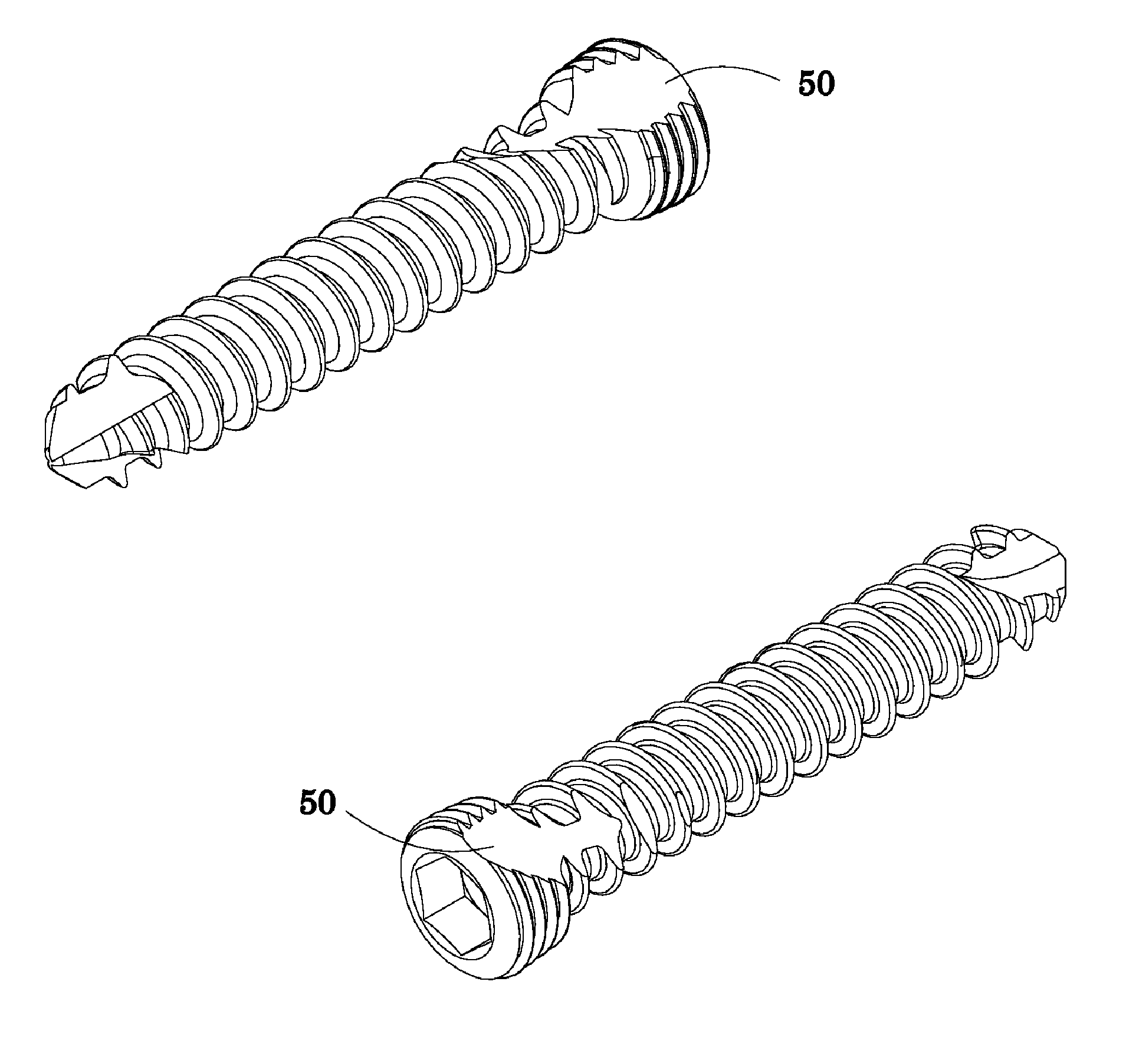
[0012]In another aspect, a method of fixating bone fractures is provided which includes positioning a bone plate having a plurality of bi-directional divergent holes therethrough to a fracture site, and inserting bone screws through the bi-directional holes of the bone plate into a bone or bone fragments to fixate the fracture, the screws being oriented in the bone in non-parallel directions. A by-pass head screw allows accommodation of a full head screw in the same hole.

Problems solved by technology

However, the angular relationship between the plate and screws is not fixed and can change postoperatively.
As such, this can lead to misalignment and poor clinical results.
However, locking screws have a limited capability to compress bone fragments.
However, for such a configuration, half of the screw holes may not be suitable for use.

Method used


Image

  • Bone fixation system
  • Bone fixation system
  • Bone fixation system

Examples


Embodiment Construction

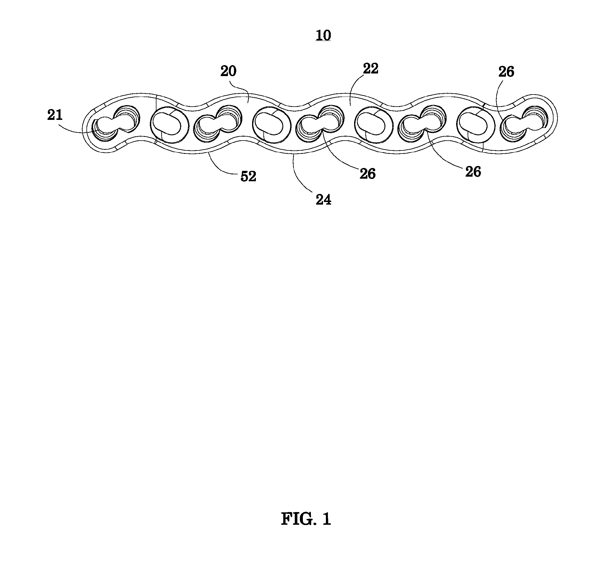
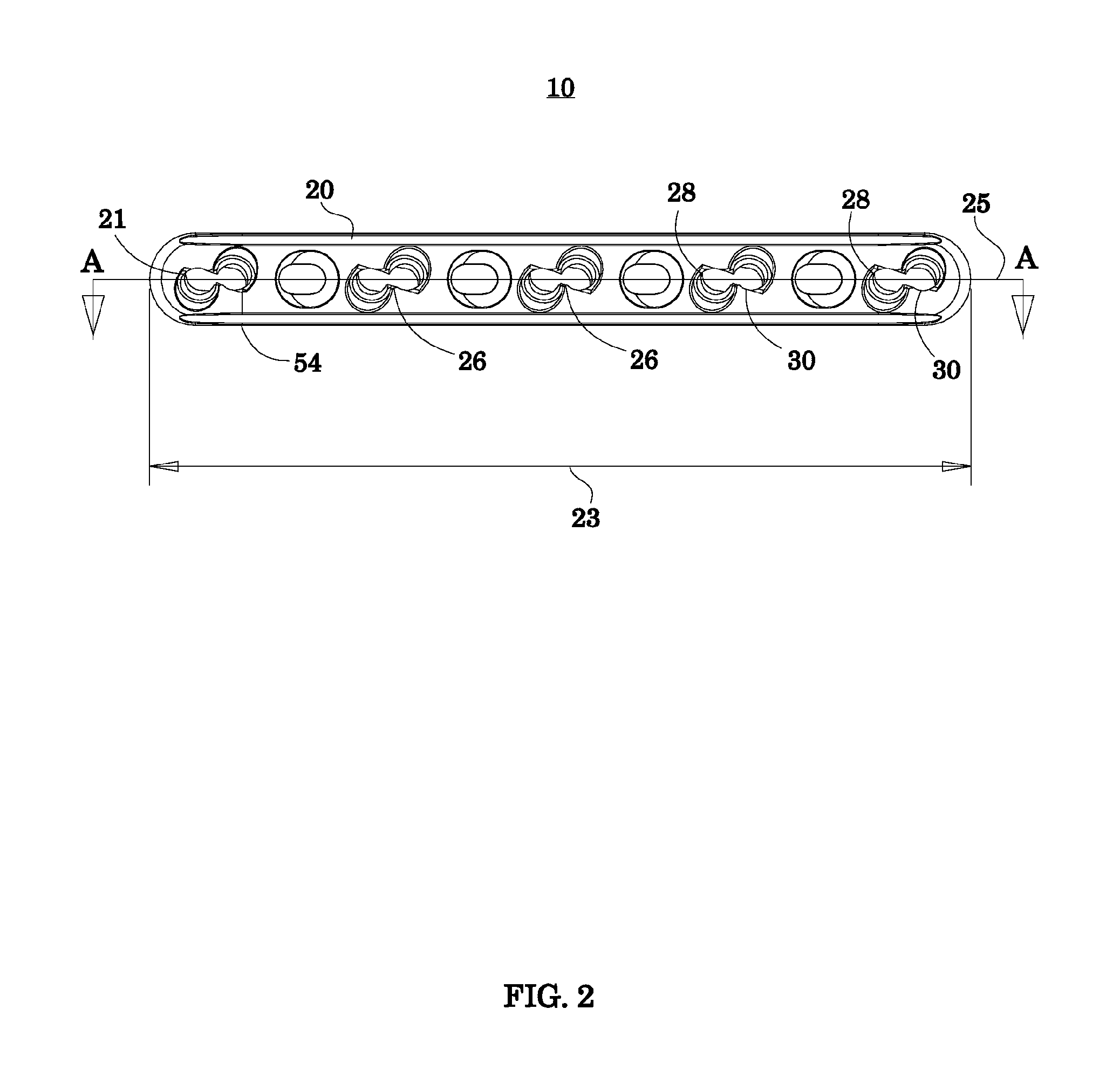
[0022]A bone fixation system embodying the principles illustrated in embodiments of the invention is provided. The system includes a bone plate and a specialized screw system.

[0023]Before any embodiments of the invention are explained in detail, it is to be understood that the invention is not limited in its application to the details of the structure and function set forth in the following description or illustrated in the appended drawings. The invention is capable of other embodiments and of being practiced or of being carried out in various ways.

[0024]Also, it is to be understood that the phraseology and terminology used herein is for the purpose of description and should not be regarded as limiting. The use of “comprising,”“including,” or “having” and variations thereof herein is meant to encompass the items listed thereafter and equivalents thereof as well as additional items. “Comprising” also encompasses the terms “consisting of” and “consisting essentially of” The use of “c...


PUM


Abstract

The invention provides embodiments of a bone fixation system having a bone plate and a specialized screws system. The bone plate includes one or more bi-directional combination holes that can accommodate two bone screws in the same hole, the screws being oriented in non-parallel direction. In accommodating two screws in the same hole, one of the screws has a by-pass head.

Description

[0001]The present application is a continuation of U.S. application Ser. No. 12 / 398,882, filed Mar. 5, 2009; which claims the benefit of U.S. Provisional Application No. 61 / 035,138, filed on Mar. 10, 2008; all of which are incorporated by reference herein.BACKGROUND OF THE INVENTION[0002]1. Field of the Invention[0003]The present invention relates to a system and method for bone fracture fixation.[0004]2. Description of the Prior Art[0005]Conventional bone fracture fixation plate and screw systems work by drawing the fracture fragments to the plate, and if designed with “compression” holes, the fracture fragments can be made to compress against each other to promote primary bone healing. However, the angular relationship between the plate and screws is not fixed and can change postoperatively. As such, this can lead to misalignment and poor clinical results.[0006]One method of securing the screw to a bone plate involves the use of so-called “locking screws.” A locking screw has a ma...

Claims


Application Information

Patent Timeline
Patent Type & Authority Applications(United States)
IPC IPC(8): A61B17/80
CPCA61B17/80A61B17/8605A61B17/8052A61B17/8014
Inventor GONZALEZ-HERNANDEZ, EDUARDO
Owner GONZALEZ HERNANDEZ EDUARDO
Why Eureka
Try Eureka