Acoustic wave device and filter

a technology of acoustic waves and filters, applied in piezoelectric/electrostrictive device details, piezoelectric/electrostrictive/magnetostrictive devices, piezoelectric/electrostriction/magnetostriction machines, etc., can solve the problems of increase production costs, and complicate manufacturing processes, so as to suppress the deterioration of resonance characteristics

Active Publication Date: 2012-08-09
TAIYO YUDEN KK
View PDF6 Cites 7 Cited by
  • Summary
  • Abstract
  • Description
  • Claims
  • Application Information

AI Technical Summary

Benefits of technology

[0006]According to an aspect of the present invention, it is an object to suppress a deterioration of the resonance characteristic.

Problems solved by technology

Such mass loading films are formed by performing a series of a film growing process, a photolithography process and an etching process multiple times. This complicates the manufacturing process and increases the production cost.
According to Documents 2 through 6, the presence of the mass loading film in the resonance portion formed by patterning increases the spurious intensity, which leads to a deterioration of the resonance characteristic.

Method used


Image

  • Acoustic wave device and filter
  • Acoustic wave device and filter
  • Acoustic wave device and filter

Examples


first embodiment

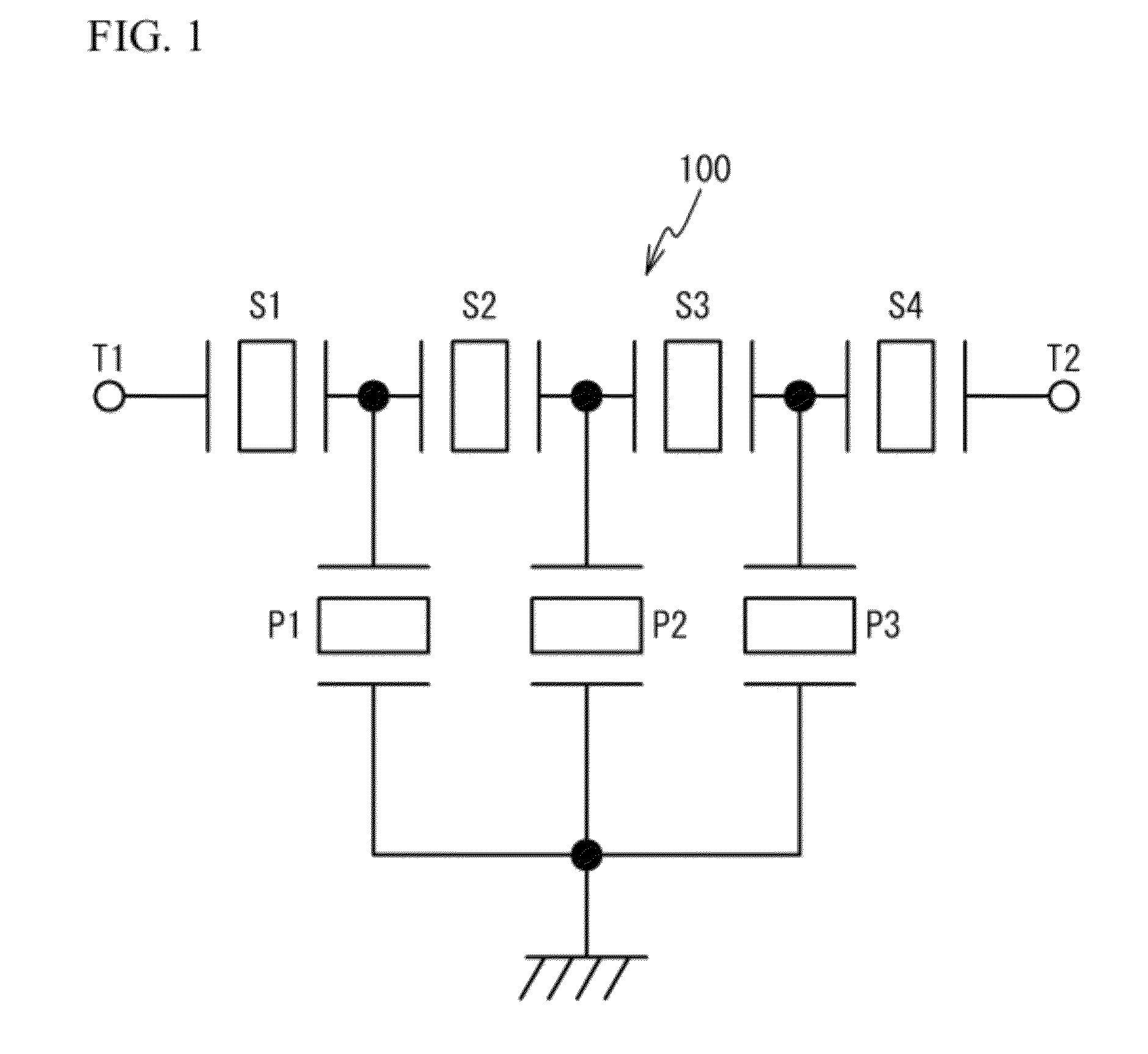
[0028]First, a description is given of an exemplary ladder type filter using an acoustic wave device in accordance with a first embodiment. FIG. 1 is a circuit diagram of such a ladder type filter. Referring to FIG. 1, a ladder type filter 100 is composed of series resonators S1˜S4 and parallel resonators P1˜P3. The series resonators S1˜S4 are connected in series with each other between an input / output terminal T1 and an input / output terminal T2. The parallel resonators P1˜P3 are connected in parallel with each other between the input / output terminals T1 and T2.

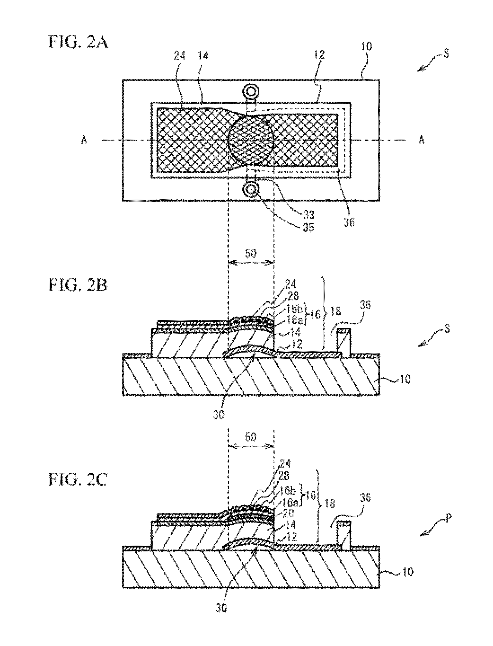
[0029]FIG. 2A is a plan view of a piezoelectric thin-film resonator in accordance with the first embodiment, FIG. 2B is a cross-sectional view taken along a line A-A in FIG. 2A in which the piezoelectric thin-film resonator is a series resonator S, and FIG. 2C is a cross-sectional view taken along the line A-A in which the resonator in FIG. 2A is a parallel resonator P. Referring to FIGS. 2A and 2B, the series resonator S is ...

second embodiment

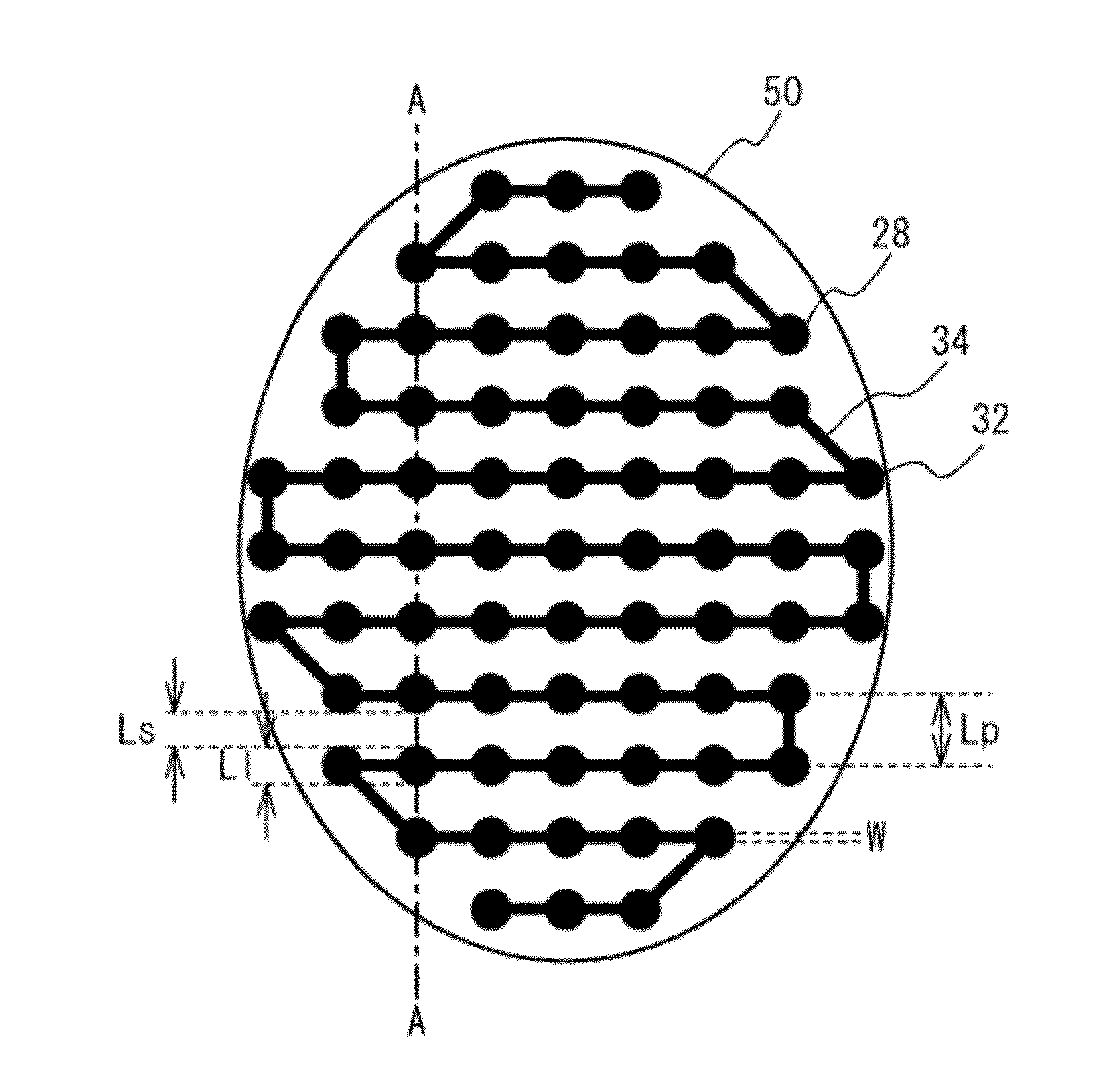
[0060]FIGS. 14A and 14B are cross-sectional views of a mass loading film of a second embodiment. As illustrated in FIG. 14A, a part of the mass loading film 28 illustrated in FIG. 3B is left. The dots of the first pattern 32 and the arms of the second pattern 34 are comparatively thick portions of the mass loading film 28. As illustrated in FIG. 14B, a part of the mass loading film illustrated in FIG. 4B is left. The dots of the first pattern 32 and the arms of the second pattern 34 are comparatively thin portions of the mass loading film 28.

third embodiment

[0061]A third embodiment has an exemplary structure having a plurality of mass loading films. FIG. 15A is a cross-sectional view of a series resonator of the third embodiment, and FIG. 15B is a cross-sectional view of a parallel resonator of the third embodiment. As illustrated in FIGS. 15A and 15B, another mass loading film 29 is formed on the frequency adjustment film 24. Like the mass loading film 28, the mass loading film 29 has the first pattern 32 and the second pattern 34.

[0062]In the first and second embodiments, when it is attempted to broaden the range in which the resonance frequency is adjusted by the single-layer mass loading film 28, the mass loading film 28 is relatively thick. According to an experiment conducted by the inventors, as the mass loading film 28 is thicker, the resonator has a worse resonance characteristic. According to the third embodiment, each of the mass loading film 28 and 29 is composed of a plurality of layers. This makes it possible for each lay...


PUM


Abstract

An acoustic wave device including: a substrate; a piezoelectric film formed on the substrate; an lower electrode provided on a first surface of the piezoelectric film; an upper electrode provided on a second surface of the piezoelectric film opposite to the first surface; and a mass loading film having a first pattern and a second pattern in a resonance portion in which the lower electrode and the upper electrode face each other through the piezoelectric film, the first pattern having portions and the second pattern having portions interlinking the portions of the first pattern.

Description

CROSS-REFERENCE TO RELATED APPLICATION[0001]This application is based upon and claims the benefit of priority of the prior Japanese Patent Application No. 2011-025488, filed on Feb. 8, 2011, the entire contents of which are incorporated herein by reference.FIELD[0002]A certain aspect of the present invention relates to acoustic wave devices and filters. Another aspect of the present invention relates to an acoustic wave device including a piezoelectric thin-film resonator and a filer using such an acoustic wave device.BACKGROUND[0003]An acoustic wave device using a piezoelectric thin-film resonator is used as a filter provided in wireless communication equipment. The piezoelectric thin-film resonator includes a film buck acoustic resonator (FBAR) and is configured to have a piezoelectric thin-film having opposite surfaces on which upper and lower electrodes are respectively provided. The resonance frequency of the piezoelectric thin-film resonator depends on the thickness of a porti...

Claims


Application Information

Patent Timeline
Patent Type & Authority Applications(United States)
IPC IPC(8): H03H9/58H01L41/04
CPCH03H3/04H03H9/02086H03H9/173H03H2003/021H03H9/582H03H2003/0471H03H2003/045H03H9/02157H03H2003/0442
Inventor TANIGUCHI, SHINJINISHIHARA, TOKIHIROYOKOYAMA, TSUYOSHISAKASHITA, TAKESHI
Owner TAIYO YUDEN KK
Why Eureka
Try Eureka