Systems and methods providing thermal spreading for an LED module

a technology of led modules and heat dissipation structures, which is applied in the direction of electrical apparatus construction details, semiconductor devices for light sources, lighting and heating apparatus, etc., can solve the problems of only having a backside heat sink, and removing heat only through the backside, and may not provide enough heat dissipation for some applications

Active Publication Date: 2012-08-09
EPISTAR CORP
View PDF2 Cites 42 Cited by
  • Summary
  • Abstract
  • Description
  • Claims
  • Application Information

AI Technical Summary

Problems solved by technology

However, there are disadvantages to having only a backside heat sink.
Also, removing the heat only through the back side may not provide enough heat dissipation for some applications.

Method used


Image

  • Systems and methods providing thermal spreading for an LED module
  • Systems and methods providing thermal spreading for an LED module
  • Systems and methods providing thermal spreading for an LED module

Examples


Embodiment Construction

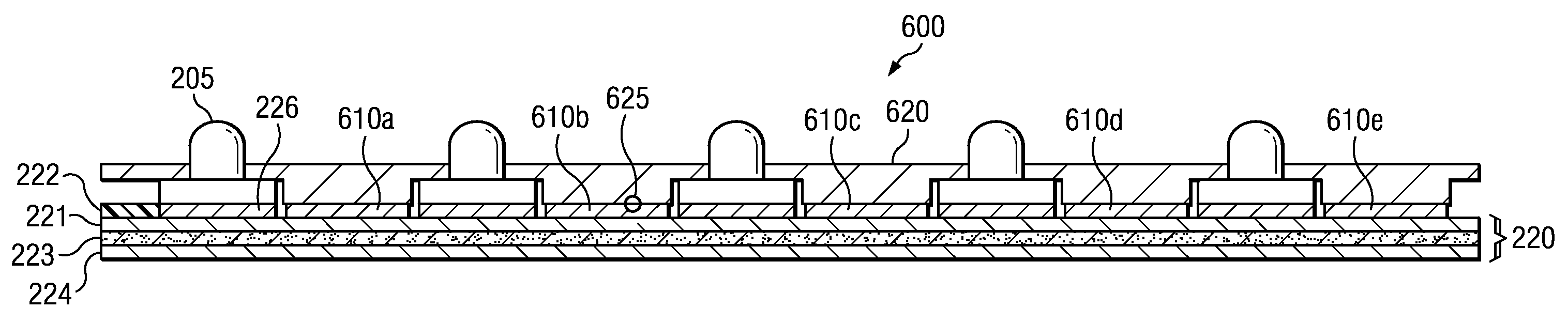
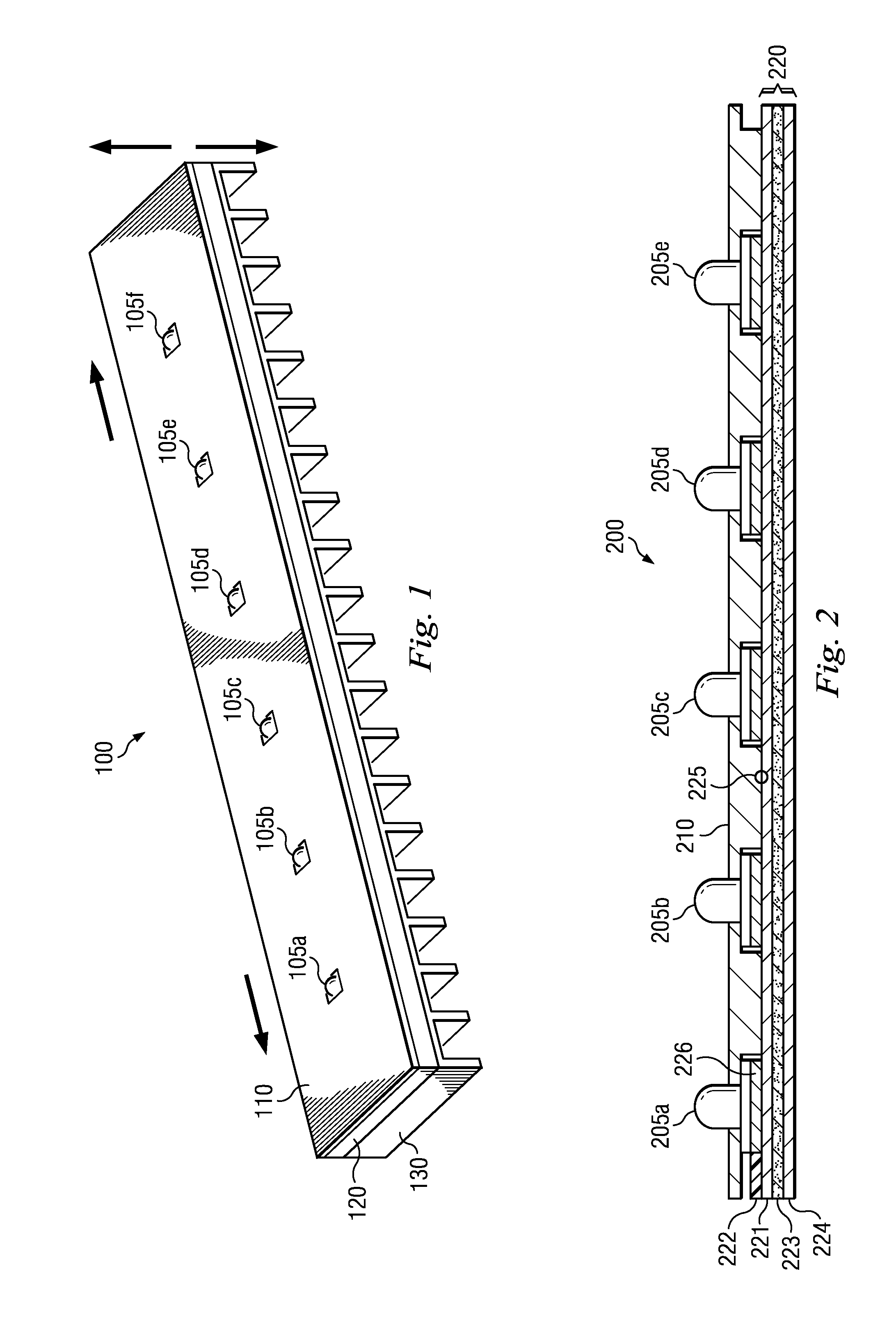
[0015]The present disclosure relates generally to LED modules. Specifically, the present disclosure relates to a front side heat spreading structure for an LED module. While the examples herein discuss applying the techniques to a Metal Core Printed Circuit Board (MCPCB), it is understood that the scope of embodiments is not limited to MCPCBs or even PCBs generally. The scope of embodiments includes all kinds of substrates for circuit layouts, including ceramic, FR-4, and the like.

[0016]The following disclosure provides many different embodiments, or examples, for implementing different features of the invention. Specific examples of components and arrangements are described below to simplify the present disclosure. These are, of course, merely examples and are not intended to be limiting. In addition, the present disclosure may repeat reference numerals and / or letters in the various examples. This repetition is for the purpose of simplicity and clarity and does not in itself dictat...


PUM

PropertyMeasurementUnit
thermalaaaaaaaaaa
thermal conductiveaaaaaaaaaa
thermally conductiveaaaaaaaaaa

Abstract

A Light Emitting Diode (LED) module includes a circuit board having a front side and a back side, a heat sink coupled to the back side of the circuit board, a thermal pad disposed on a front side of the circuit board, an LED disposed on the front side of the circuit board. The LED is in thermal contact with the thermal pad. The module further includes a heat spreading device placed over the thermal pad and in thermal contact with the thermal pad.

Description

BACKGROUND[0001]The present disclosure relates generally to Light Emitting Diode (LED) module manufacturing. Specifically, the present disclosure relates to systems and methods that provide a front-side heat spreading structure for an LED module.[0002]Many conventional systems mount LEDs to circuit boards. Such circuit boards have a front side, where the LEDs are mounted, and a backside opposite the front side. LEDs can produce heat, so some conventional systems include mechanisms to remove the heat. One example of a system to remove the heat is a heat sink mounted to the back side of the circuit board. The heat can be moved from the front side LED to the backside heat sink using a thermal via or a thermal pad and an intermediate layer of thermal conductive material.[0003]However, there are disadvantages to having only a backside heat sink. For instance, structures to move the heat from the front side to the back side take up space on and within the circuit board. Also, removing the...

Claims


Application Information

Patent Timeline
Patent Type & Authority Applications(United States)
IPC IPC(8): H05K7/20H05K3/30
CPCF21Y2101/02Y10T29/4913H05K1/0203H05K1/056H05K1/111H05K3/0061H05K2201/066H05K2201/10106H05K2201/10969F21V29/20F21K9/30F21V29/22F21V29/70F21V29/763F21Y2103/003F21K9/20F21Y2103/10F21Y2115/10
Inventor YEH, WEI-YUSUN, CHIH-HSUAN
Owner EPISTAR CORP
Why Eureka
Try Eureka