Fanned vent cover insert

Inactive Publication Date: 2012-08-09
RUDD STEVEN
View PDF20 Cites 5 Cited by
  • Summary
  • Abstract
  • Description
  • Claims
  • Application Information

AI Technical Summary

Benefits of technology

[0008]The principles of the present invention further provide for an air handling system having a fanned vent cover insert for increasing air flow. The air handling system includes an air processing unit, such as a furnace or an air conditioner, which processes air and blows the processed air out. An air duct receives the processed and passes it to its air exhaust. The fanned vent cover insert receives air from the air exhaust and increases its flow. The fanned vent cover

Problems solved by technology

But, if the blower output splits into multiple ducts or if an air vent is a long way from a blower motor significant pressure drops can occur which can seriously reduce the air output.
However, that can involve significant additional costs for a larger blower motor as well as any additional electrical power that would be required to drive the blower motor.
Furthermore, simply increasing the b

Method used


Image

  • Fanned vent cover insert
  • Fanned vent cover insert
  • Fanned vent cover insert

Examples


Example

[0016]The presently disclosed subject matter now will be described more fully hereinafter with reference to the accompanying drawings in which one embodiment is shown. However, it should be understood that this invention may take many different forms and thus should not be construed as being limited to the embodiment set forth herein. In the figures like numbers refer to like elements throughout.

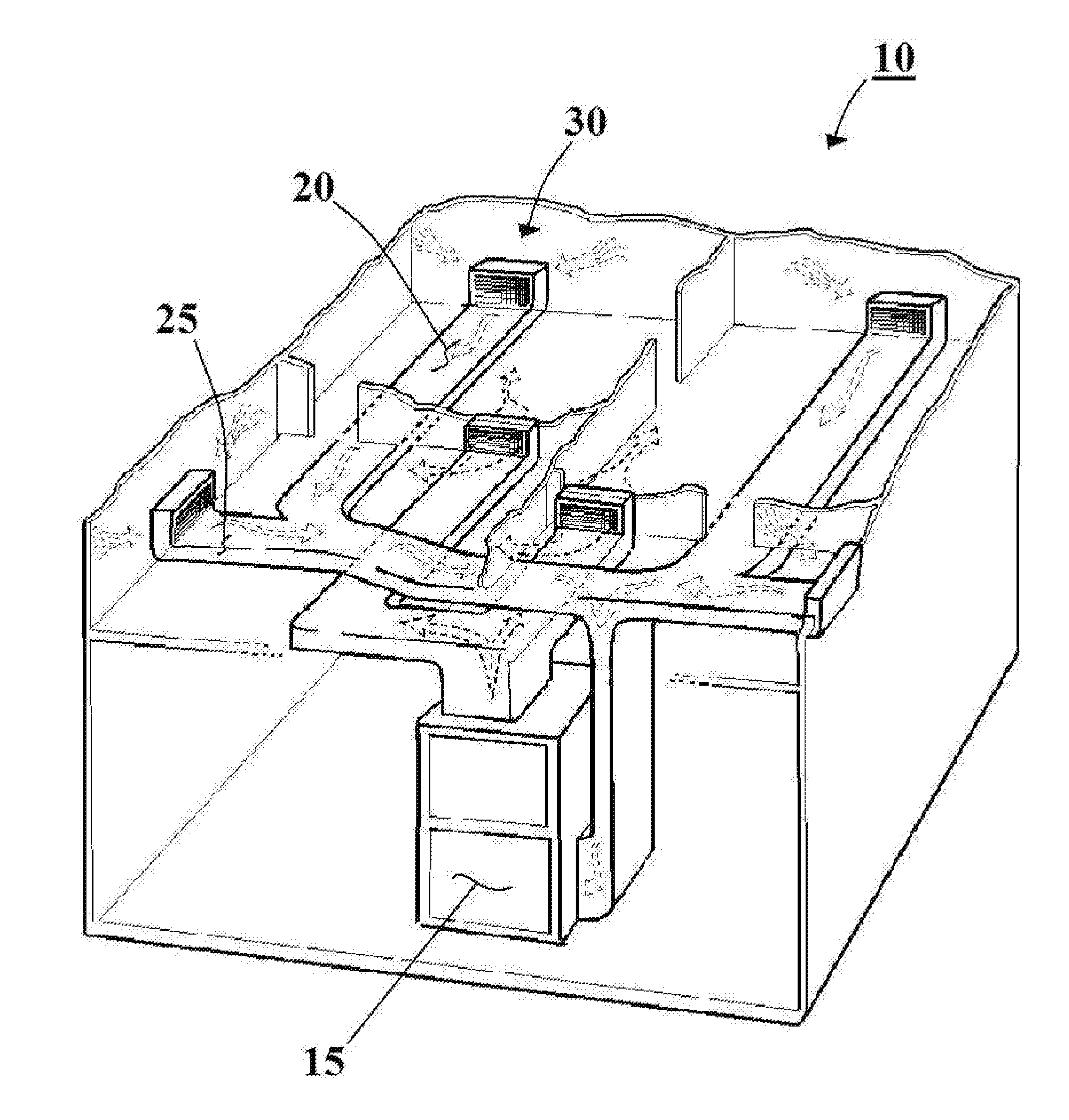
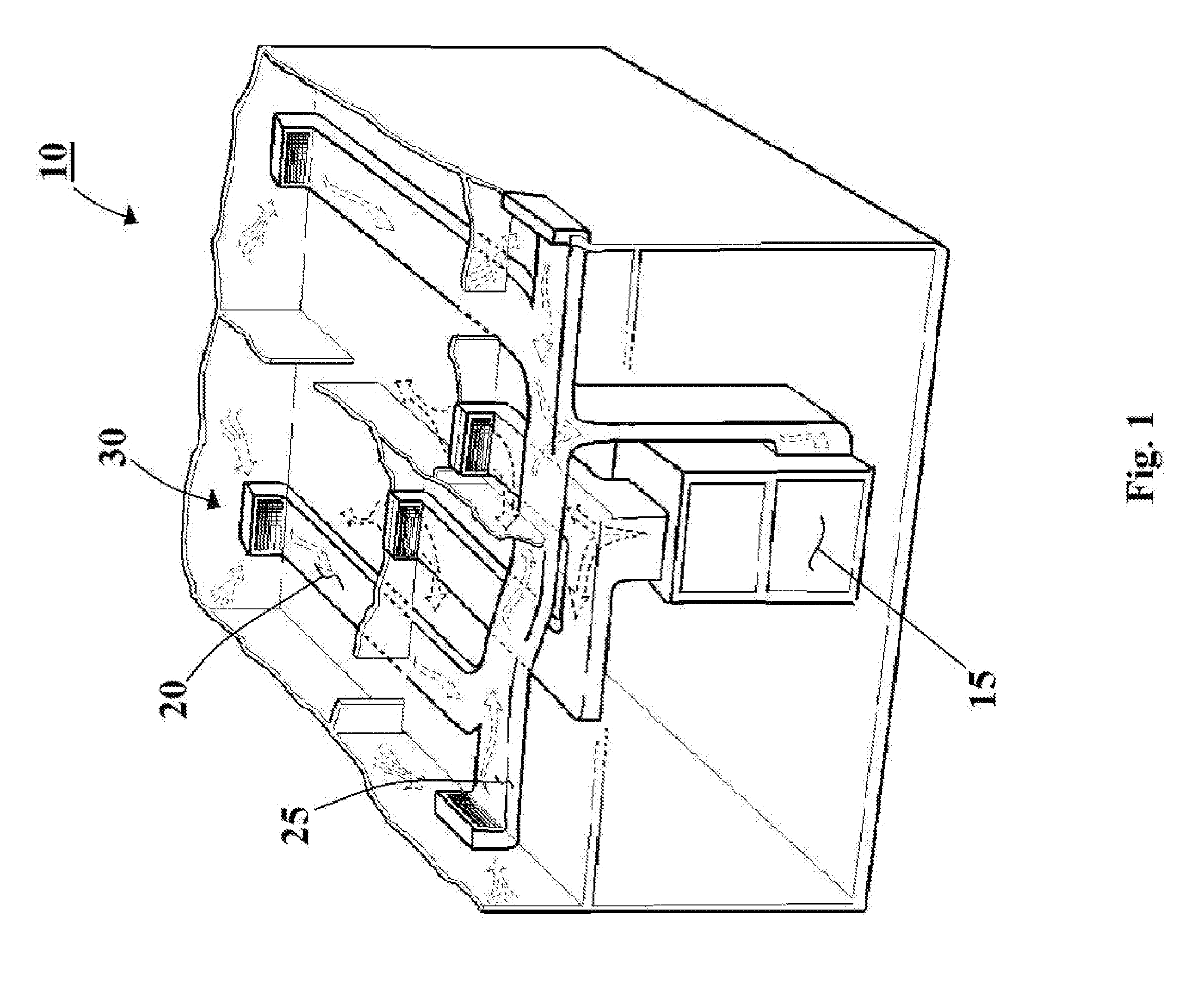
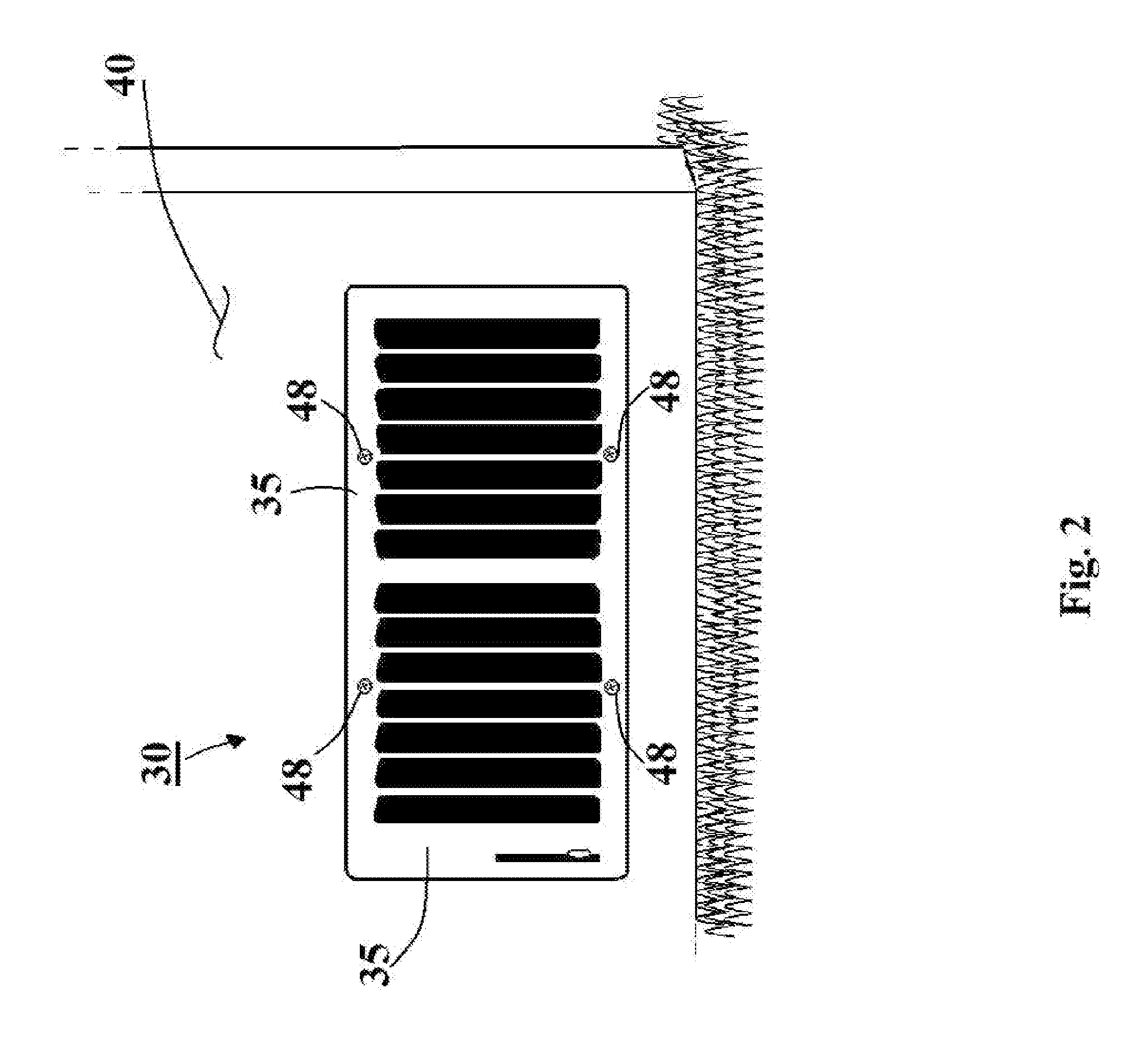
[0017]The present invention is described herein with reference to FIGS. 1 to 6. Specifically, the present invention is described as a fanned vent cover insert that is suitable for insertion between an air vent and an air duct exhaust. The fanned vent cover insert is for increasing air flow from an air ducting system without increasing the size of a given blower motor and without requiring modification to existing electrical power distribution.

[0018]FIG. 1 illustrates an air handling system 10 that is in accord with the principles of the present invention. The air handling system 10 includes ...


PUM


Abstract

A fanned vent cover insert, and an air handing system having such a fanned vent cover insert, for increasing air flow from an air vent. The fanned vent cover insert includes a battery and a direct current motor-generator having a rotor. A fan is attached to the rotor. A blower switch selectively connects the battery to the motor-generator so as to selectively cause the fan to move air. A battery charger is connected to the motor-generator and to the battery. The battery charger charges the battery when air moves the fan when the motor is not turning the fan.

Description

FIELD OF THE INVENTION[0001]The presently disclosed subject matter is directed towards a fanned vent cover insert for assisting air flow from an air duct into a room.BACKGROUND OF THE INVENTION[0002]Forced air heating and cooling has been successfully used for many years in many different applications. Such systems incorporate fanned blower motors that blow hot air from a furnace or cold air from an air conditioner through an air duct and out an air vent into a room. By adding numerous air duct branches to the system multiple areas can be heated and cooled from a central furnace / air conditioner.[0003]Forced air heating and cooling works particularly well when the air ducting system does not include too many duct branches and when all air vents are close to the blower motor. But, if the blower output splits into multiple ducts or if an air vent is a long way from a blower motor significant pressure drops can occur which can seriously reduce the air output.[0004]A prior art approach t...

Claims


Application Information

Patent Timeline
IPC IPC(8): F24F7/06
CPCF24F7/06F24F13/082
Inventor RUDD, STEVEN
Owner RUDD STEVEN
Why Eureka
Try Eureka