Device For Ventilating A Compartment

a ventilation device and compartment technology, applied in the direction of combustion air/fuel air treatment, machines/engines, transportation and packaging, etc., can solve the problems of reducing the performance of the aircraft, and increasing the dimensions and weight of the fire extinguishing system, so as to improve the quality of the guiding of the air flow

Inactive Publication Date: 2012-08-16
AIRBUS OPERATIONS (SAS)
View PDF2 Cites 6 Cited by
  • Summary
  • Abstract
  • Description
  • Claims
  • Application Information

AI Technical Summary

Benefits of technology

[0014]Preferably, the walls of the air distributor are placed at a distance of at least 1 cm from the walls of the air diffuser, to permit an air flow distribution which limits the pressure drops caused by the distributor. Preferably, also, the walls of the air distributor are at a distance of between 3 and 6 cm from the walls of the air diffuser, to achieve a compromise between the limitation of the pressure drops of the distributor and an optimal direction of the air flow.
[0015]According to one aspect of the invention, the air distributor includes vanes arranged to distribute the air flow vertically and horizontally. Thus the air flow is distributed within the compartment according to the desired result. Since the distributor is independent of the diffuser, the configuration of the distributor vanes can be freely determined, thus improving the quality of the guiding of the air flow by the distributor.

Problems solved by technology

One of the principal drawbacks of a prior art ventilation device is that the air distributor creates large pressure drops, which adversely affect the performance of the ventilation device, and, more generally, that of the aircraft.
However, this solution has the drawback of increasing the parasitic drag of the intake, which reduces the performance of the aircraft.
However, this requires an increase in the dimensions and weight of the fire extinguishing system, and consequently of the aircraft itself, which is disadvantageous.

Method used


Image

  • Device For Ventilating A Compartment
  • Device For Ventilating A Compartment

Examples


Embodiment Construction

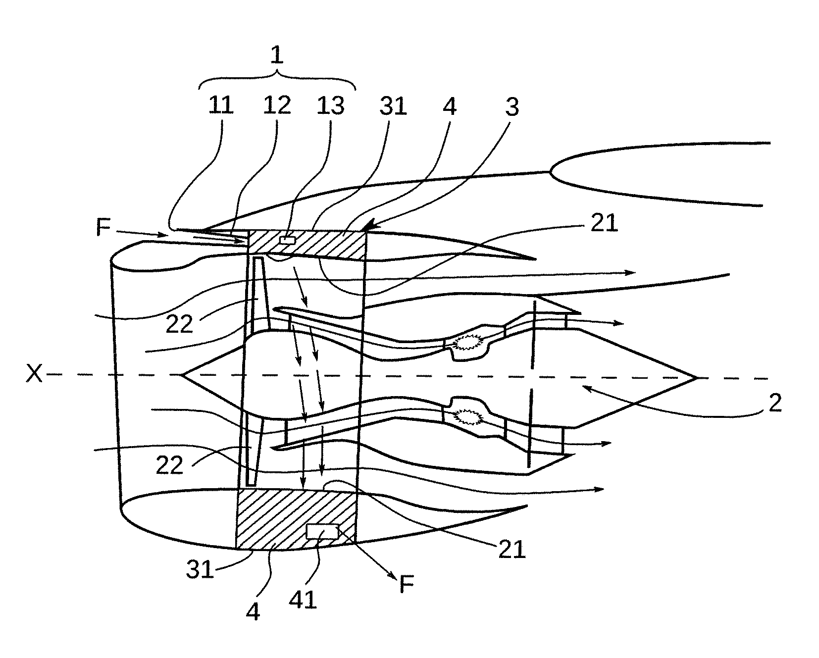
[0023]A description is given below of a ventilation device 1 according to the invention for ventilating a compartment 4 of an aircraft engine 2, the engine 2 extending in an axial direction X shown in FIG. 1. In this example, since the engine 2 is mounted in a nacelle 3, the ventilation device 1 according to the invention is arranged to ventilate a compartment 4 delimited by the casing 21 of the engine 2 and by the cowling 31 of the nacelle 3. The compartment 4, shown by hatching in FIG. 1, forms an annular volume located between the casing 21 of the engine 2 and the nacelle 3. In this example, the compartment 4 is delimited internally by the fan casing of the engine 2 in which fan blades 22 are driven.

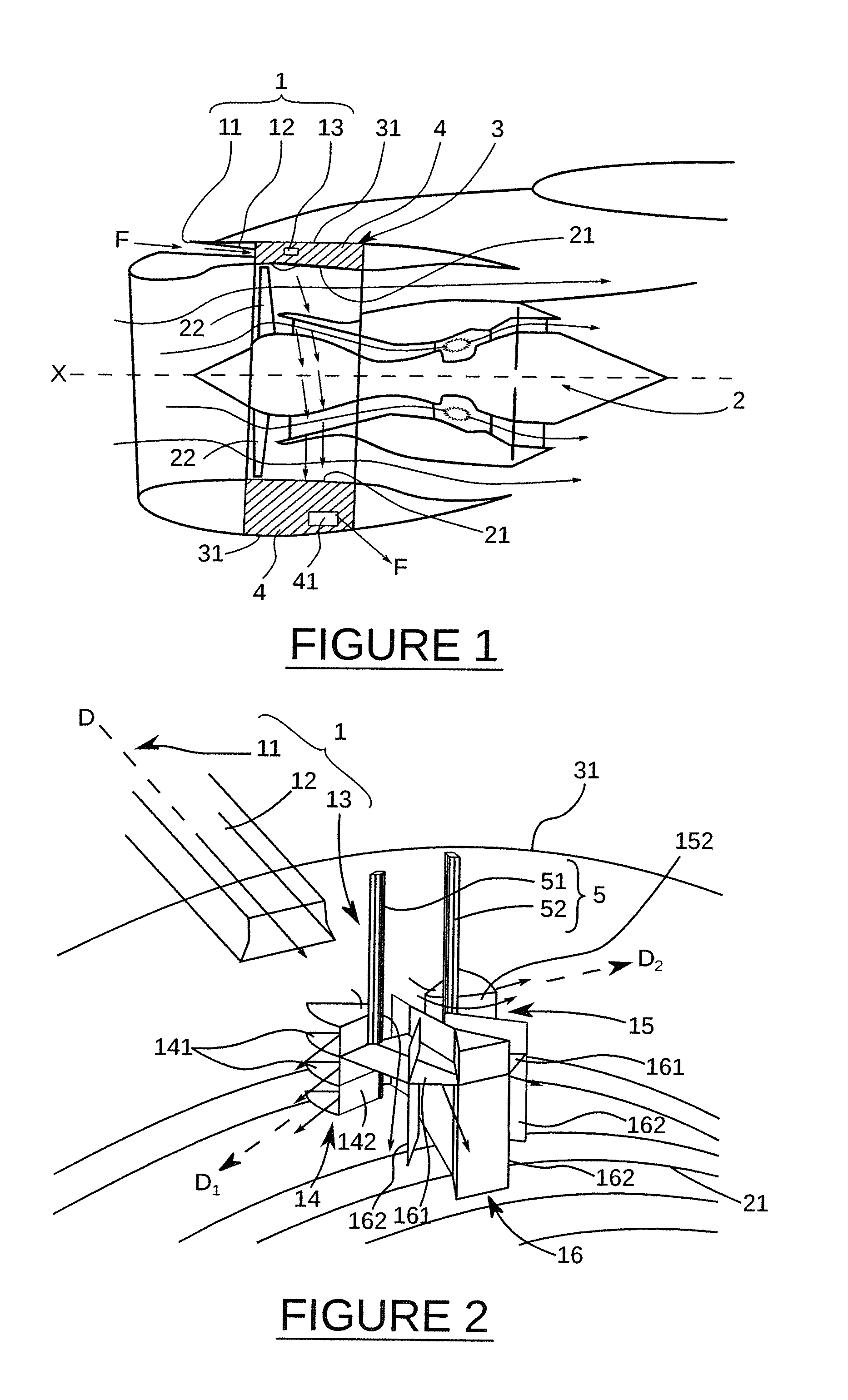
[0024]As shown schematically in FIG. 1, the ventilation device 1, located in an upper part of the compartment 4, includes an air intake 11 adapted to capture an air flow F outside the engine 2, an air diffuser 12 adapted to guide the air flow F into the compartment 4, and an air distr...


PUM


Abstract

A ventilation device for a compartment, preferably a compartment of an aircraft engine, the device including an air intake adapted to capture a flow of air outside the compartment, an air diffuser adapted to guide the air flow into the compartment, and an air distributor adapted to distribute the air flow within the compartment, the air distributor in this device being separated from the air diffuser, and being placed inside the compartment at a distance from the air diffuser

Description

TECHNICAL FIELD[0001]The invention relates to the field of ventilating a compartment, that is to say a volume delimited by a plurality of partitions, by circulating a flow of air in the compartment. More specifically, the aim of the invention is to provide ventilation of at least one aircraft engine compartment by circulating a flow of air drawn from outside the engine.[0002]An aircraft engine conventionally includes a plurality of compartments which have to be ventilated in order to cool the components located in each compartment, for example, or in order to renew the air so as to remove any fuel vapour from the compartment.[0003]In order to renew the air in an engine compartment, a flow of air must be taken from outside the compartment, guided into the compartment, and finally directed within the compartment to achieve the desired result (cooling, removal of fuel vapours, etc.). For this purpose, a conventional ventilation device is made, in a known way, in the form of a one-piece...

Claims


Application Information

Patent Timeline
Patent Type & Authority Applications(United States)
IPC IPC(8): F02C7/04
CPCB64D2241/00B64D33/08Y10T137/0536
Inventor SOMMERER, YANNICK
Owner AIRBUS OPERATIONS (SAS)
Why Eureka
Try Eureka