

Method and an arrangement for controlling fluid flow into a production pipe
- Summary
- Abstract
- Description
- Claims
- Application Information
AI Technical Summary
Benefits of technology
Problems solved by technology
Method used
Image

Examples
first embodiment
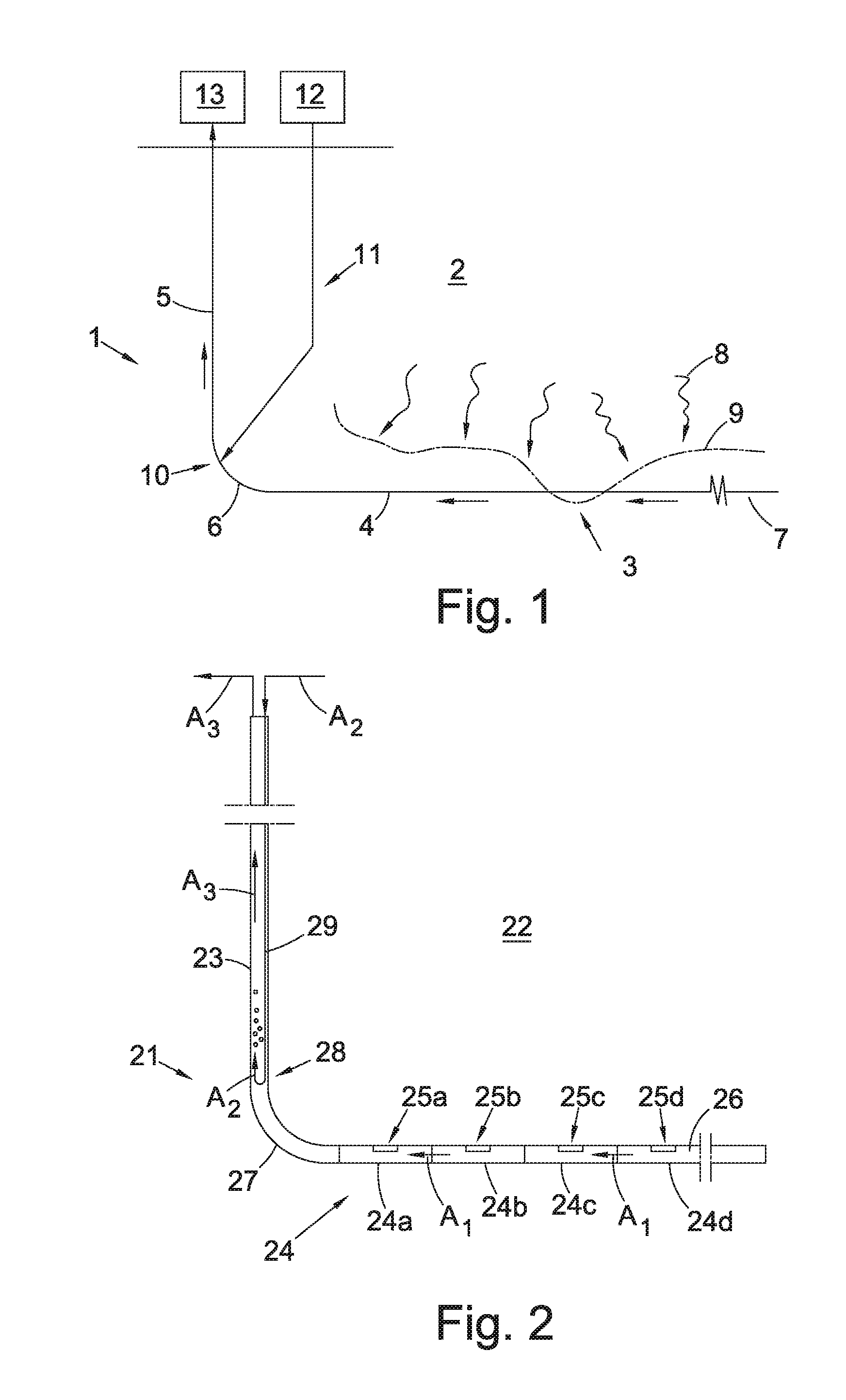
[0044]FIG. 2 shows a schematic view of a production pipe 21 according to the invention. The production pipe 21 is arranged to control the inflow of a fluid from a formation along a length of the production pipe, such as a drainage pipe 24 draining fluid from a reservoir formation 22. The drainage pipe 24 comprises multiple sections 24a, 24b, 24c, 24d (four shown), each provided with one or more inflow control devices 25a, 25b, 25c, 25d (one shown per section) which connects the geological production formation 22 with an internal flow space 26 of the drainage pipe 24. The production pipe 21 further comprises an upper production pipe, or riser 23, for removing or collecting the fluid from the drainage pipe 24, and a heel section 27 connecting the riser 23 and the drainage pipe 24. The drainage pipe 24 extends between the heel 27 and a toe of said production pipe. The direction of flow in the drainage pipe 24 towards the heel 27 is indicated by arrows A1.
[0045]The production pipe also ...
second embodiment
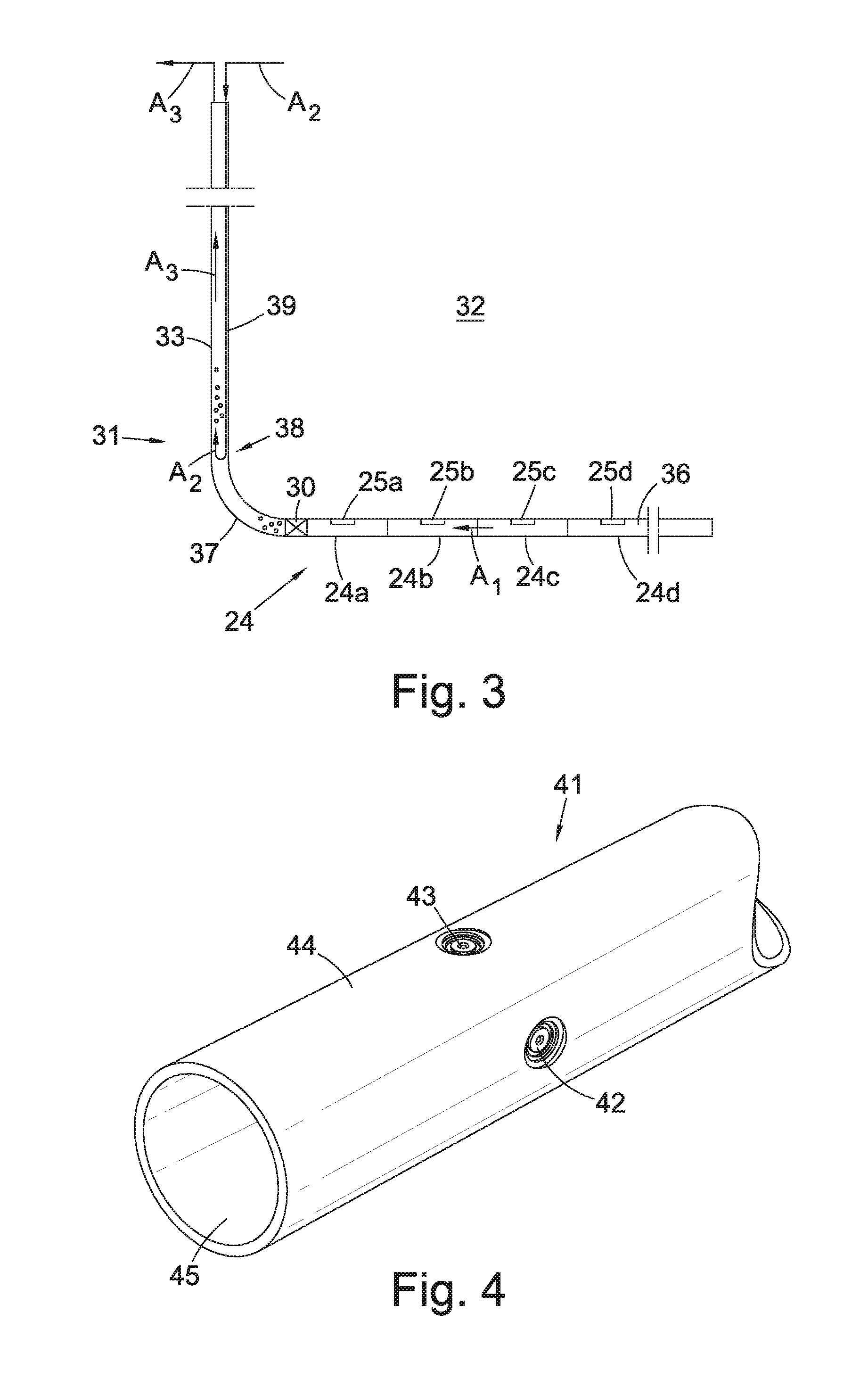
[0049]FIG. 3 shows a schematic view of a production pipe 31 according to the invention. The production pipe 31 is arranged to control the inflow of a fluid from a formation along a length of the production pipe, such as a drainage pipe 34 draining fluid from a reservoir formation 32. The drainage pipe 34 comprises multiple sections 34a, 34b, 34c, 34d (four shown), each provided with one or more inflow control devices 35a, 35b, 35c, 35d (one shown per section) which connects the geological production formation 32 with an internal flow space 36 of the drainage pipe 34. The production pipe 31 further comprises an upper production pipe, or riser 33, for removing or collecting the fluid from the drainage pipe 34, and a heel section 37 connecting the riser 33 and the drainage pipe 34. The drainage pipe extends between the heel 37 and a toe of said production pipe. The direction of flow in the drainage pipe 34 towards the heel 37 is indicated by arrows A1.
[0050]The production pipe also com...
PUM
 Abstract
Description
Claims
Application Information