Method for producing sterile cryogenic liquid

a cryogenic liquid and cryogenic liquid technology, applied in the direction of lighting and heating apparatus, filtration, solidification, etc., can solve the problems of difficult pre-sterilization of the system, complicated piping and valves, etc., and achieve the effect of rapid sterilization with steam

Inactive Publication Date: 2011-11-17
LINDE AG
View PDF3 Cites 0 Cited by
  • Summary
  • Abstract
  • Description
  • Claims
  • Application Information

AI Technical Summary

Benefits of technology

[0009]An important property that the discharge orifice should possess is its ability to be steam sterilized. Unlike a needle valve, the orifice should have no traps or pockets like a needle valve and can be readily sterilized with steam. The orifice should provide a reproducible and constant flow restriction that will offer a controlled pressure drop along the line leading to the orifice.

Problems solved by technology

This generally introduces piping and valve complexities, and makes it difficult to pre-sterilize the system (typically using steam).

Method used


Image

  • Method for producing sterile cryogenic liquid
  • Method for producing sterile cryogenic liquid
  • Method for producing sterile cryogenic liquid

Examples


Embodiment Construction

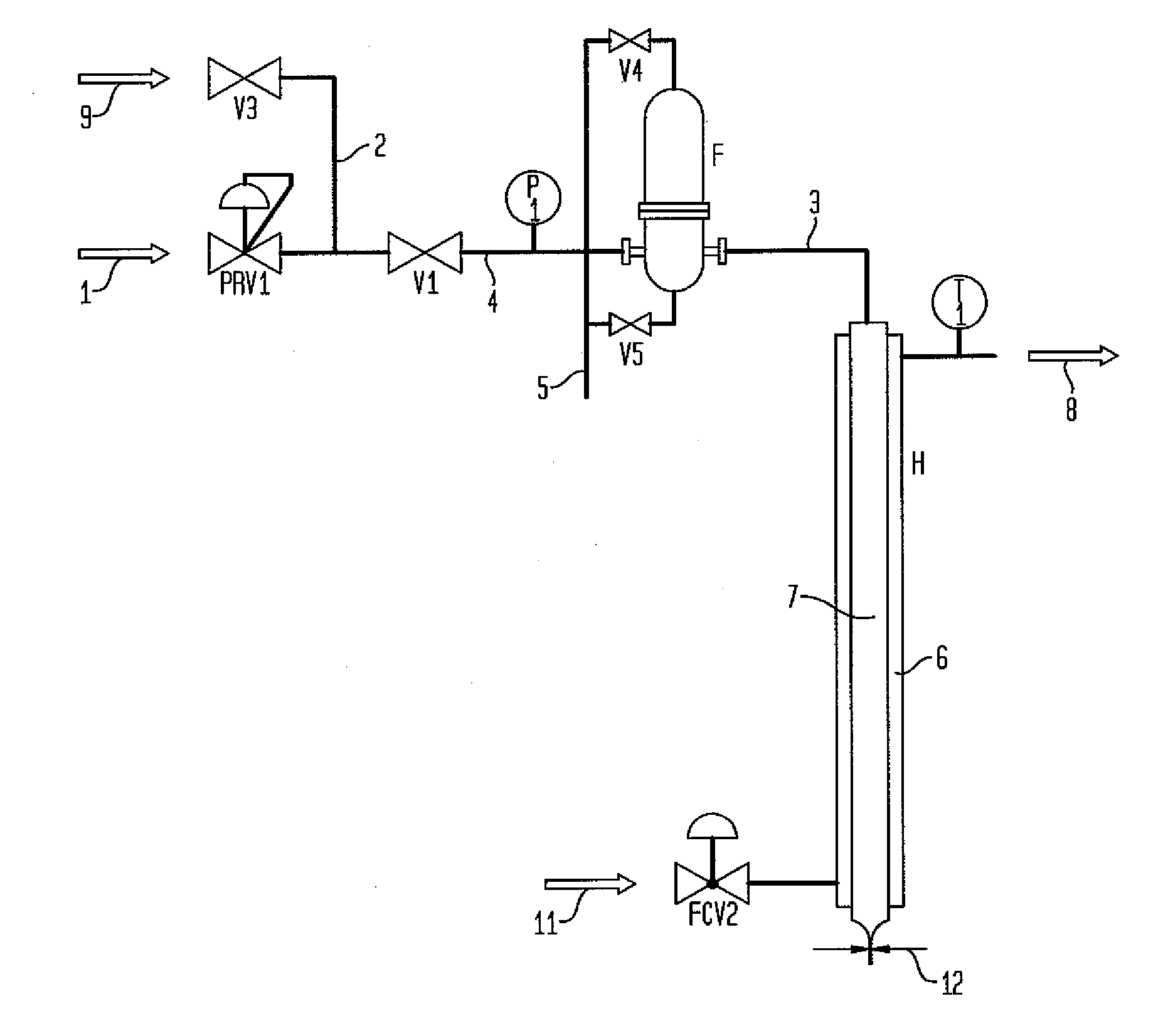
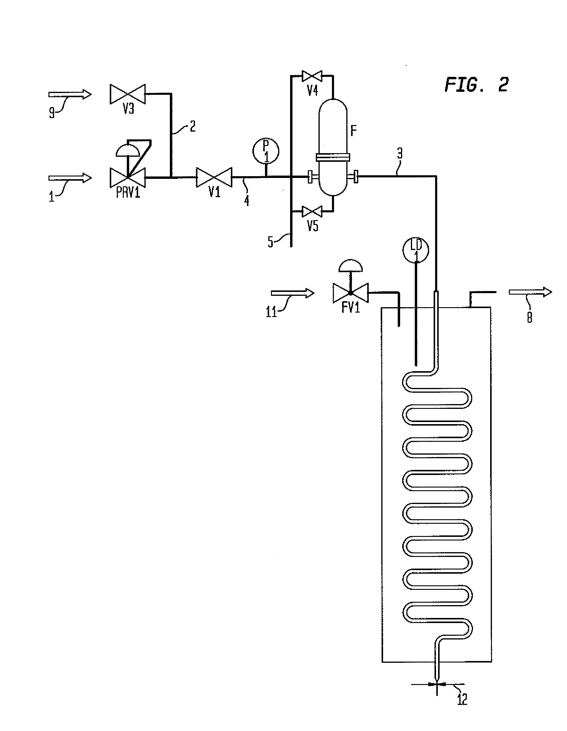
[0014]The present invention provides for optimizing the discharge rate of a sterile cryogenic fluid from a sterile cryogenic fluid production process by determining the optimum discharge orifice size based upon a predetermined flow rate and pressure of the sterile cryogenic fluid.

[0015]The method of the present invention is illustrated using a specific example. FIG. 1 provides a simple arrangement where the object is to produce a flow of sterile liquid nitrogen for delivery at atmospheric pressure. Normal gaseous nitrogen 1 at a predetermined pressure is fed through valve PRV1 to a standard sterilizing filter to produce a sterile nitrogen gas stream 3. This sterile nitrogen gas stream is then fed through a simple tube in tube heat exchanger H where it is liquefied 7 through indirect heat exchange with a liquid nitrogen cooling stream 6 which is at close to atmospheric pressure. The key element of the present invention is the smooth orifice 12 that is placed at the discharge of the s...


PUM


Abstract

A method for producing a sterile cryogenic fluid from a cryogenic gas by sterilizing the cryogenic gas and using a heat exchanger to liquefy the sterile cryogenic stream. The discharge rate of the sterile cryogenic fluid is controlled by sizing the discharge orifice and setting a predetermined pressure of the sterile cryogenic fluid.

Description

BACKGROUND OF THE INVENTION[0001]The present invention relates to a method and apparatus for the production of a sterile cryogenic fluid such as liquid nitrogen. The invention employs an improved pressure and flow control arrangement which significantly reduces the complexity of the system and the validation requirements for steam sterilization.[0002]Earlier methods for the production of sterile cryogenic fluids such as liquid nitrogen have generally used two broad approaches. The first method uses direct liquid filtration (down to about 0.2 micron or less) to remove microbial or other contaminants. The second method also uses filtration to about 0.2 micron or less, but starts by filtering warm gas. This sterile warm gas is then liquefied in an indirect heat exchange process with a suitable low temperature refrigerant. This low temperature refrigerant is generally liquid having the same chemical composition as the sterile gas (e.g., nitrogen). In this case it is necessary to maintai...

Claims


Application Information

Patent Timeline
Patent Type & Authority Applications(United States)
IPC IPC(8): F25J1/00
CPCA61L2/04A61L2/022
Inventor LEE, RON C.
Owner LINDE AG
Why Eureka
Try Eureka